車道檢測(Advanced Lane Finding Project)
實現步驟:
- 使用提供的一組棋盤格圖片計算相機校正矩陣(camera calibration matrix)和失真系數(distortion coefficients).
- 校正圖片
- 使用梯度閾值(gradient threshold),顏色閾值(color threshold)等處理圖片得到清晰捕捉車道線的二進制圖(binary image).
- 使用透視變換(perspective transform)得到二進制圖(binary image)的鳥瞰圖(birds-eye view).
- 檢測屬於車道線的像素並用它來測出車道邊界.
- 計算車道曲率及車輛相對車道中央的位置.
- 處理圖片展示車道區域,及車道的曲率和車輛位置.
相機校正(Camera Calibration)
這里會使用opencv提供的方法通過棋盤格圖片組計算相機校正矩陣(camera calibration matrix)和失真系數(distortion coefficients)。首先要得到棋盤格內角的世界坐標"object points"和對應圖片坐標"image point"。假設棋盤格內角世界坐標的z軸為0,棋盤在(x,y)面上,則對於每張棋盤格圖片組的圖片而言,對應"object points"都是一樣的。而通過使用openCv的cv::findChessboardCorners(),傳入棋盤格的灰度(grayscale)圖片和橫縱內角點個數就可得到圖片內角的"image point"。
void get_obj_img_points(const vector<string> & images,const cv::Size & grid,const cv::Size& distance,cv::Mat& cameraMatirx,cv::Mat& distCoeffs){
    cv::Mat img,gray;//灰度圖像
    vector<cv::Point2f> corners;//用來儲存t圖片角點
    vector<cv::Point3f> object_point;//保存標定板上所有角點坐標
    vector<cv::Mat> rvecs,tvecs;//旋轉向量和位移向量
    vector<vector<cv::Point3f>> object_points;//棋盤格三維坐標容器
    vector<vector<cv::Point2f>> img_points;//棋盤格角點容器
    for(auto & imgdir:images){
        //載入圖像
        img=cv::imread(imgdir);
        //生成object points
        for(int i=0;i<grid.height;i++){
            for(int j=0;j<grid.width;j++){
                object_point.push_back(cv::Point3f(i*distance.width,j*distance.height,0));//向容器存入每個角點坐標
            }
        }
        //得到灰度圖片
        cv::cvtColor(img,gray,cv::COLOR_BGR2GRAY);
        //得到圖片的image points
        //NOTE corners的儲存方式為從左往右,從上往下每行儲存,所以儲存object_point的時候需從grid。width開始遍歷儲存
        bool ret=cv::findChessboardCorners(gray,grid,corners,cv::CALIB_CB_ADAPTIVE_THRESH+cv::CALIB_CB_NORMALIZE_IMAGE+cv::CALIB_CB_FAST_CHECK);
        if(ret){//亞像素精細化
            cv::cornerSubPix(gray,corners,cv::Size(11,11),cv::Size(-1,-1),
            cv::TermCriteria(cv::TermCriteria::COUNT+cv::TermCriteria::EPS, 30, 0.1));
            img_points.push_back(corners);
            object_points.push_back(object_point);
        }
        object_point.clear();//清空object_point以便下一幅圖使用該容器
        //繪制角點並顯示
        cv::drawChessboardCorners(img,grid,cv::Mat(corners),ret);
        // cv::imshow("chessboard corners",img);
        // cv::waitKey(10);
    }
    cv::calibrateCamera(object_points,img_points,img.size(),cameraMatirx,distCoeffs,rvecs,tvecs);
}
然后使用上方法得到的object_points and img_points 傳入cv::calibrateCamera() 方法中就可以計算出相機校正矩陣(camera calibration matrix)和失真系數(distortion coefficients),再使用 cv::undistort()方法就可得到校正圖片。
def cal_undistort(img, objpoints, imgpoints):
    ret, mtx, dist, rvecs, tvecs = cv2.calibrateCamera(objpoints, imgpoints, img.shape[1::-1], None, None)
    dst = cv2.undistort(img, mtx, dist, None, mtx)
    return dst
以下為其中一張棋盤格圖片校正前后對比:

校正測試圖片
代碼如下:
//獲取棋盤格圖片
get_images_by_dir(cal_dir,filetype,imgs);
//計算矯正系數
get_obj_img_points(imgs,grid,distance,cameraMatirx,distCoeffs);
測試圖片校正前后對比:
![alt text][(https://raw.githubusercontent.com/RyanAdex/CarND-Advanced-Lane-Lines/master/output_images/undistortion.png)
閾值過濾(thresholding)
這里會使用梯度閾值(gradient threshold),顏色閾值(color threshold)等來處理校正后的圖片,捕獲車道線所在位置的像素。(這里的梯度指的是顏色變化的梯度)
以下方法通過"cv::Sobel()"方法計算x軸方向或y軸方向的顏色變化梯度導數,並以此進行閾值過濾(thresholding),得到二進制圖(binary image):
void abs_sobel_thresh(const cv::Mat& src,cv::Mat& dst,const char& orient='x',const int& thresh_min=0,const int& thresh_max=255){
    cv::Mat src_gray,grad;
    cv::Mat abs_gray;
    //轉換成為灰度圖片
    cv::cvtColor(src,src_gray,cv::COLOR_RGB2GRAY);
    //使用cv::Sobel()計算x方向或y方向的導
    if(orient=='x'){
        cv::Sobel(src_gray,grad,CV_64F,1,0);
        cv::convertScaleAbs(grad,abs_gray);
    }
    if(orient=='y'){
        cv::Sobel(src_gray,grad,CV_64F,0,1);
        cv::convertScaleAbs(grad,abs_gray);
    }
    //二值化
    cv::inRange(abs_gray,thresh_min,thresh_max,dst);
    // cv::threshold(abs_gray,dst,thresh_min,thresh_max,cv::THRESH_BINARY|cv::THRESH_OTSU);
}
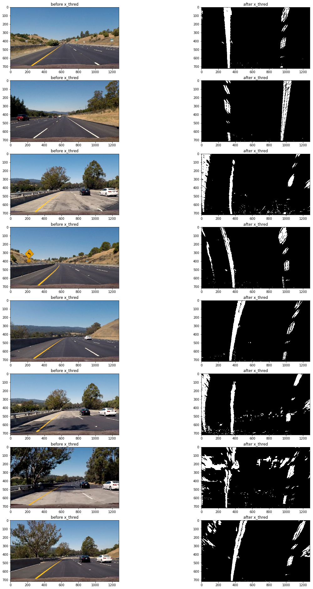
通過測試發現使用x軸方向閾值在35到100區間過濾得出的二進制圖可以捕捉較為清晰的車道線:
abs_sobel_thresh(imge,absm,'x',55,200);//sobel邊緣識別
以下為使用上面方法應用測試圖片的過濾前后對比圖:
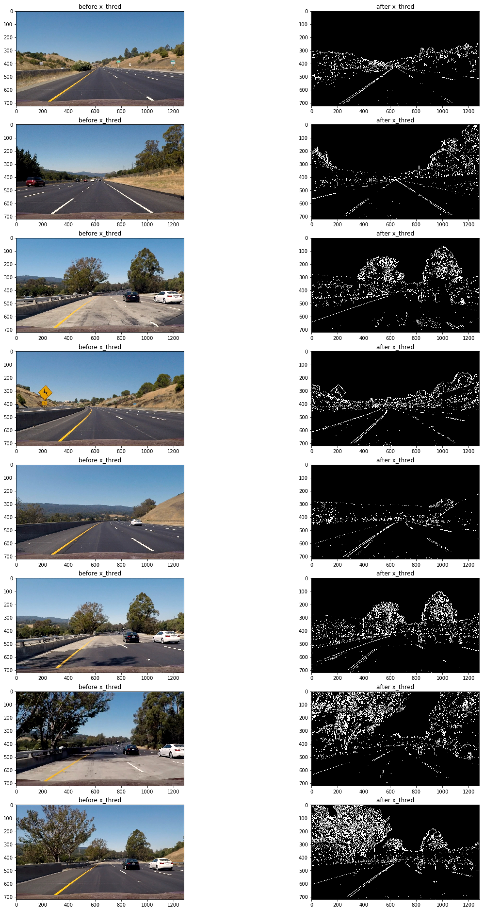
可以看到該方法的缺陷是在路面顏色相對較淺且車道線顏色為黃色時,無法捕捉到車道線(第三,第六,第七張圖),但在其他情況車道線捕捉效果還是不錯的。
接下來測試一下使用全局的顏色變化梯度來進行閾值過濾:
void mag_thresh(const cv::Mat& src,cv::Mat& dst,const int& sobel_kernel=3,const int& thresh_min=0,const int& thresh_max=255){
    cv::Mat src_gray,gray_x,gray_y,grad;
    cv::Mat abs_gray_x,abs_gray_y;
    //轉換成為灰度圖片
    cv::cvtColor(src,src_gray,cv::COLOR_RGB2GRAY);
    //使用cv::Sobel()計算x方向或y方向的導
    cv::Sobel(src_gray,gray_x,CV_64F,1,0,sobel_kernel);
    cv::Sobel(src_gray,gray_y,CV_64F,0,1,sobel_kernel);
    //轉換成CV_8U
    cv::convertScaleAbs(gray_x,abs_gray_x);
    cv::convertScaleAbs(gray_y,abs_gray_y);
    //合並x和y方向的梯度
    cv::addWeighted(abs_gray_x,0.5,abs_gray_y,0.5,0,grad);
    //二值化
    cv::inRange(grad,thresh_min,thresh_max,dst);
    // cv::threshold(grad,dst,thresh_min,thresh_max,cv::THRESH_BINARY|cv::THRESH_OTSU);

}
mag_thresh(imge,mag,3,45,150);
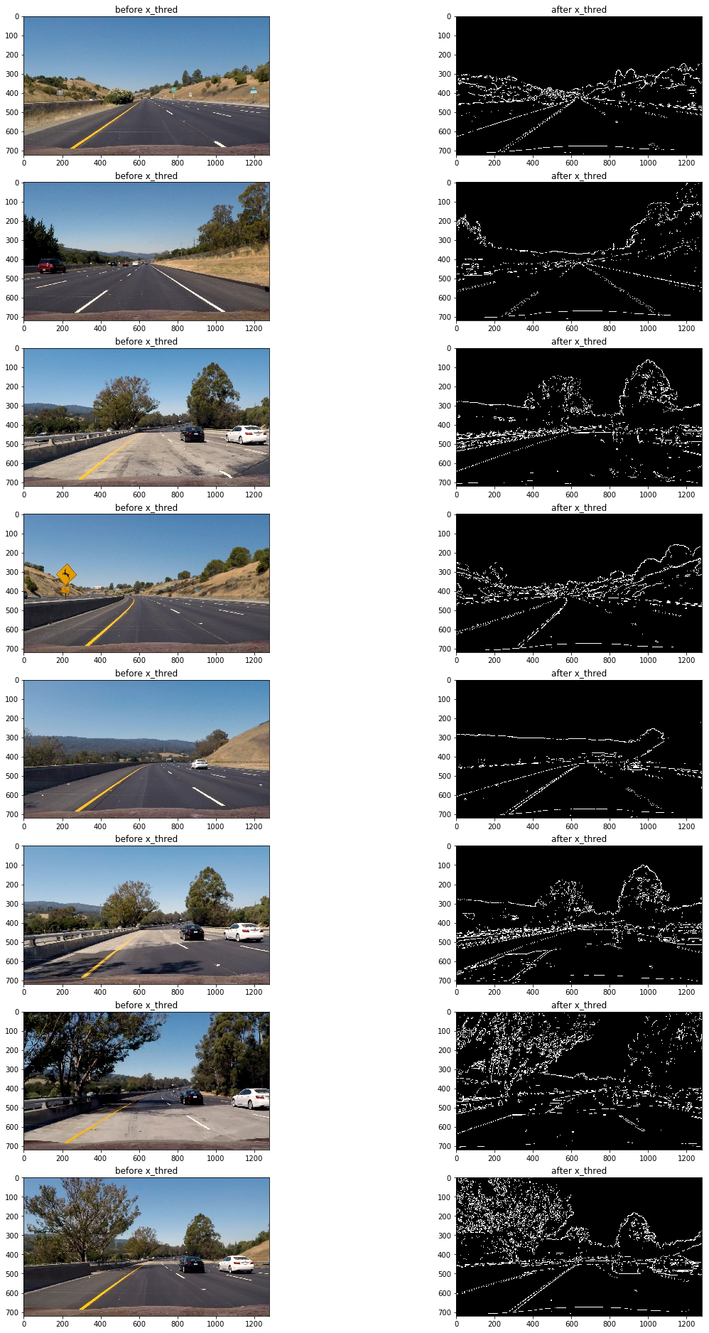
結果仍然不理想(觀察第三,第六,第七張圖片),原因是當路面顏色相對較淺且車道線顏色為黃色時,顏色變化梯度較小,想要把捕捉車道線需要把閾值下限調低,然而這樣做同時還會捕獲大量的噪音像素,效果會更差。
那么使用顏色閾值過濾呢?
下面為使用hls顏色空間的s通道進行閾值過濾:
void hls_select(const cv::Mat& src,cv::Mat& dst,const char& channel='s',const int& thresh_min=0,const int& thresh_max=255){
    cv::Mat hls,grad;
    vector<cv::Mat> channels;
    cv::cvtColor(src,hls,cv::COLOR_RGB2HLS);
    //分離通道
    cv::split(hls,channels);
    //選擇通道
    switch (channel)
    {
        case 'h':
            grad=channels.at(0);
            break;
        case 'l':
            grad=channels.at(1);
            break;
        case 's':
            grad=channels.at(2);
            break;
        default:
            break;
    }
    //二值化
    cv::inRange(grad,thresh_min,thresh_max,dst);
    // cv::threshold(grad,dst,thresh_min,thresh_max,cv::THRESH_BINARY);
}
mag_thresh(imge,mag,3,45,150);
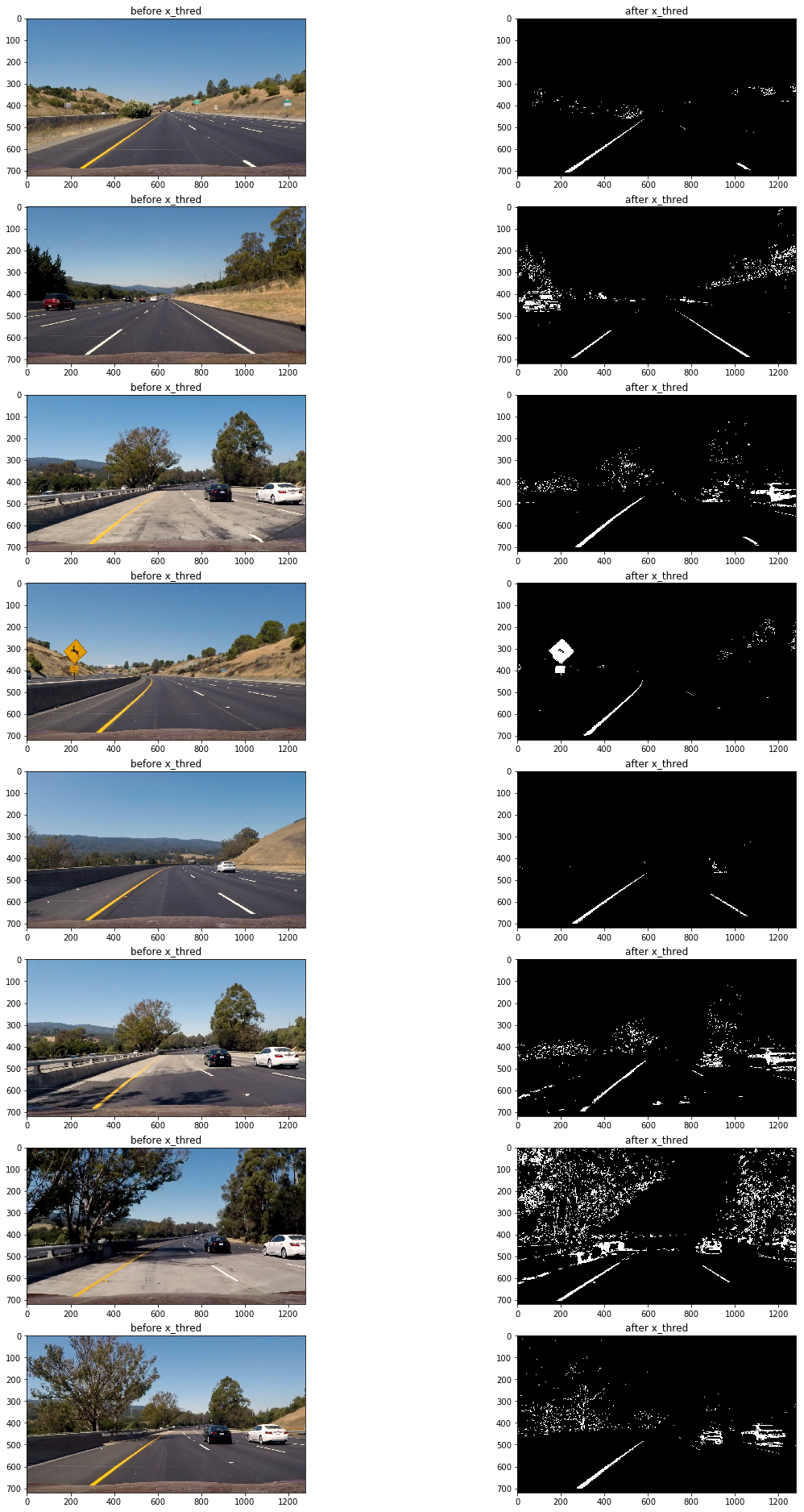
可以看到在路面顏色相對較淺且車道線顏色為黃色的區域,車道線仍然被清晰的捕捉到了,然而在其他地方表現卻不太理想(第四,第八張圖片)
因此為了應對多變的路面情況,需要結合多種閾值過濾方法。
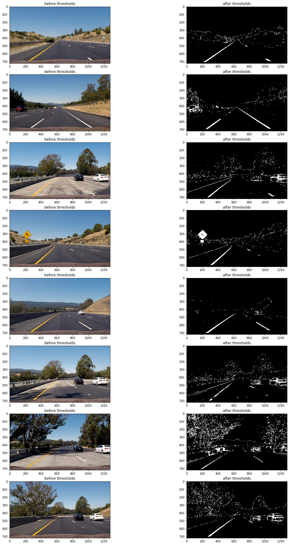
以下為最終的閾值過濾組合:
abs_sobel_thresh(imge,absm,'x',55,200);//sobel邊緣識別
mag_thresh(imge,mag,3,45,150);
hls_select(imge,hls,'s',160,255);
dir_threshold(imge,dir,3,0.7,1.3);
luv_select(imge,luv,'l',180,255);
// lab_select(imge,lab,'b',126,127);

imgout=(absm&mag&luv)|(hls&luv);
透視變換(perspective transform)
這里使用"cv::getPerspectiveTransform()"來獲取變形矩陣(tranform matrix),把閾值過濾后的二進制圖片變形為鳥撒視角。
以下為定義的源點(source points)和目標點(destination points)
| Source | Destination |
|---|---|
| 585, 460 | 320, 0 |
| 203, 720 | 320, 720 |
| 1127, 720 | 960, 720 |
| 695, 460 | 960, 0 |
定義方法獲取變形矩陣和逆變形矩陣:
void get_M_Minv(const vector<cv::Point2f>& src,const vector<cv::Point2f>& dst,cv::Mat& M,cv::Mat& Minv){
    M=cv::getPerspectiveTransform(src,dst);
    Minv=cv::getPerspectiveTransform(dst,src);
}
然后使用"cv::warpPerspective()"傳入相關值獲得變形圖片(wrapped image)
cv::warpPerspective(cimg,imge,M,img.size(),cv::INTER_LINEAR);
以下為原圖及變形后的效果:
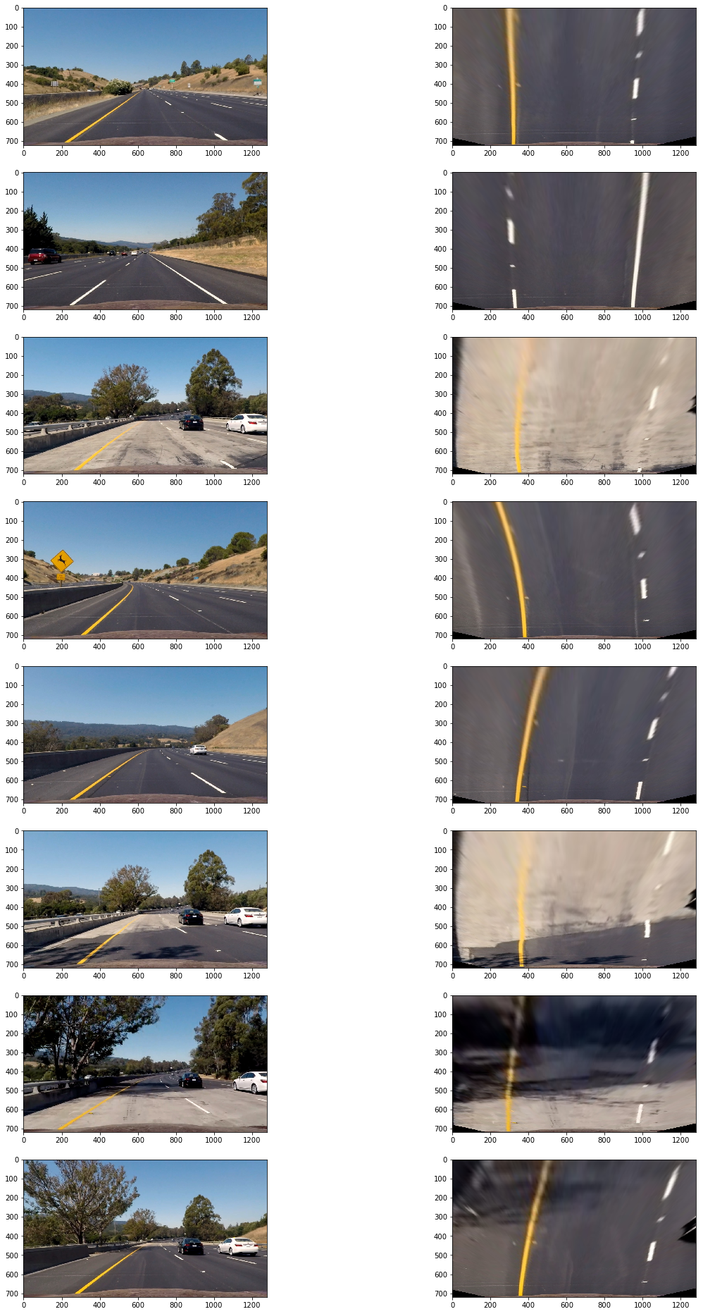
以下為閾值過濾后二進制圖變形后效果:
檢測車道邊界
上面的二進制圖還存在一定的噪音像素,為了准確檢測車道邊界,首先要確定哪些像素是屬於車道線的。
首先要定位車道線的基點(圖片最下方車道出現的x軸坐標),由於車道線在的像素都集中在x軸一定范圍內,因此把圖片一分為二,左右兩邊的在x軸上的像素分布峰值非常有可能就是車道線基點。
以下為測試片x軸的像素分布圖:
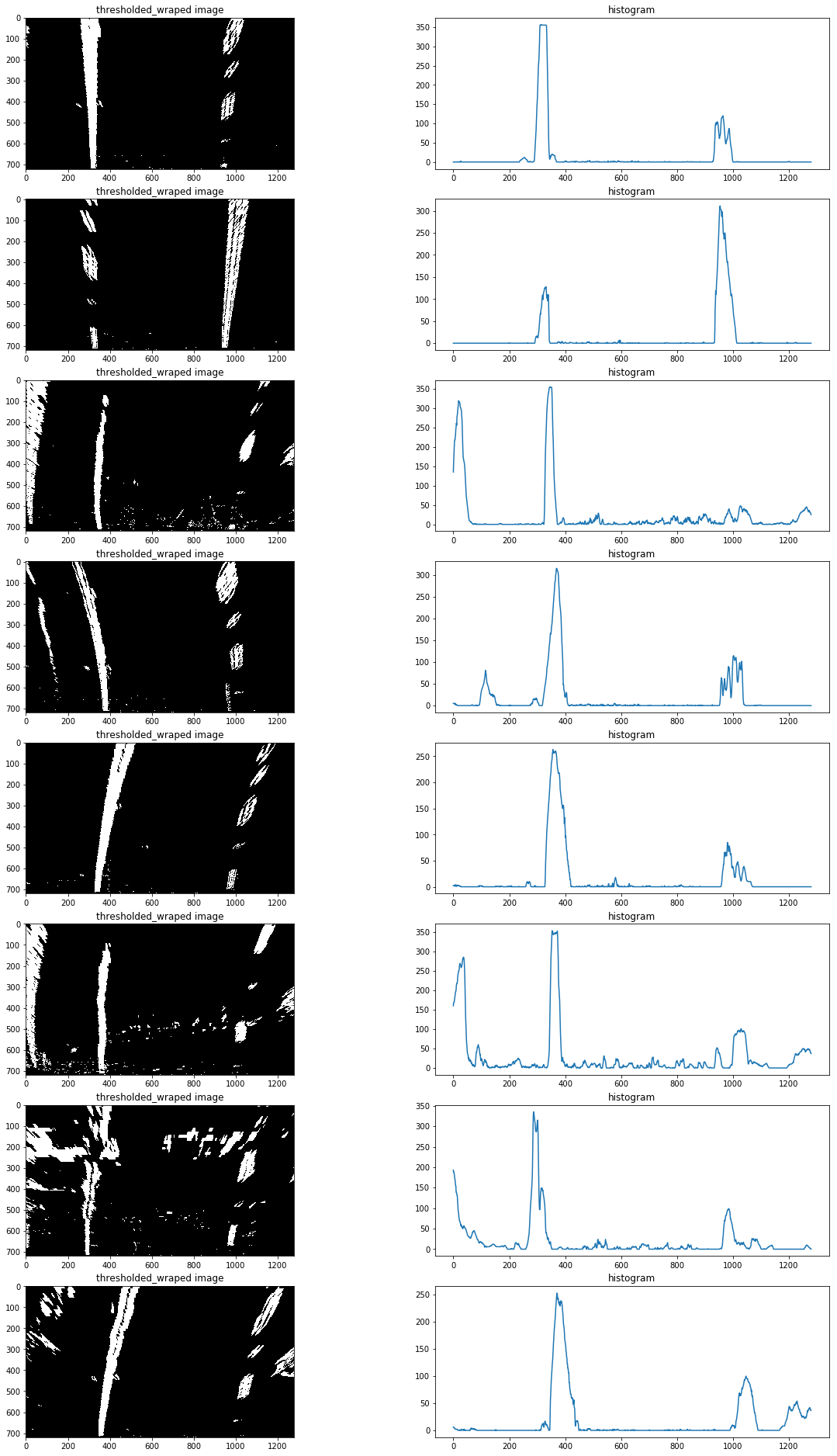
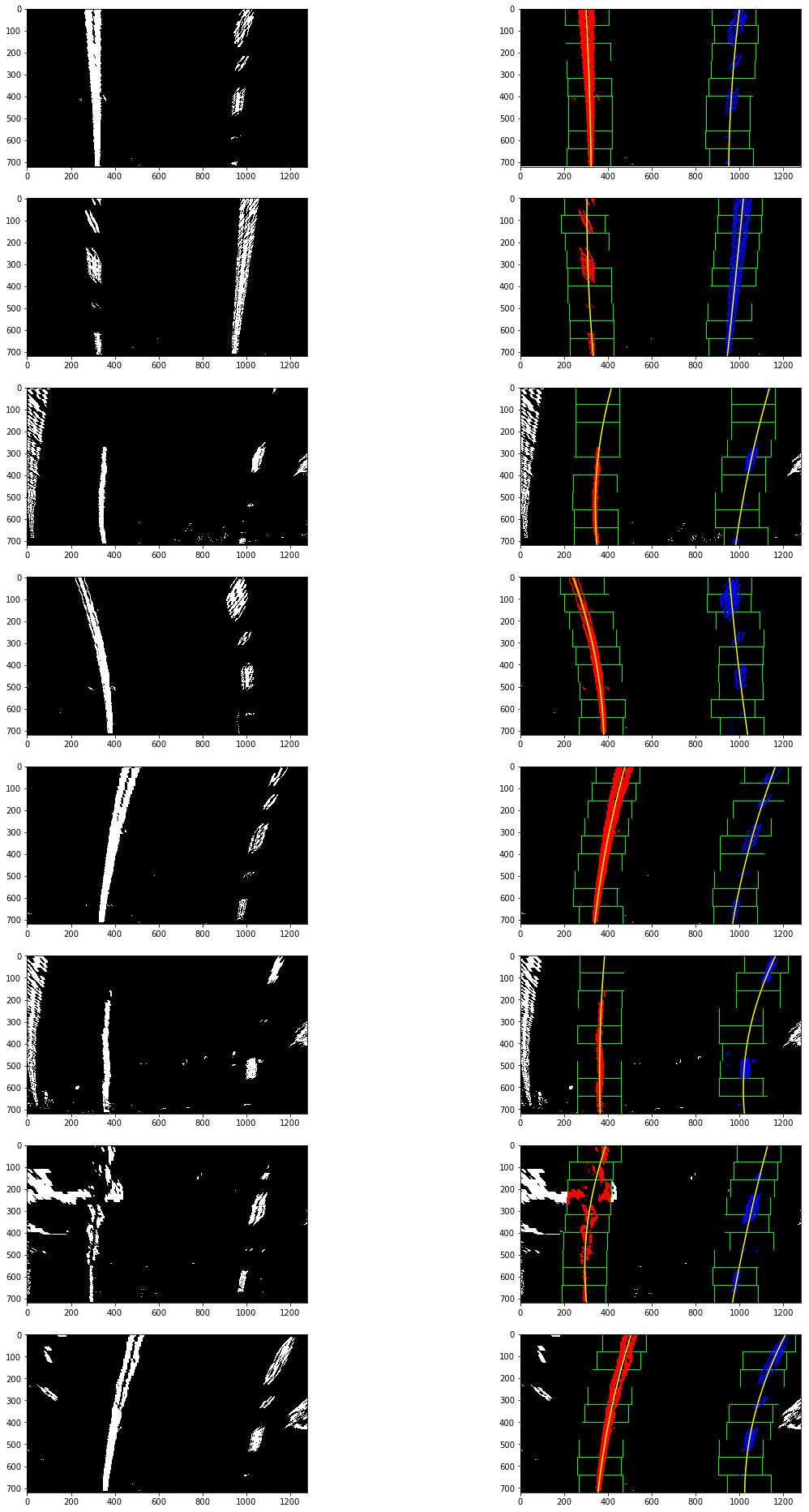
定位基點后,再使用使用滑動窗多項式擬合(sliding window polynomial fitting)來獲取車道邊界。這里使用9個200px寬的滑動窗來定位一條車道線像素:
void find_line(const cv::Mat& src,vector<cv::Point>& lp,vector<cv::Point>& rp,int& rightx_current,int& leftx_current,double& distance_from_center){
    cv::Mat hist,nonzero,l,r;
    vector<cv::Point> nonzerol,nonzeror,lpoint,rpoint;
    int midpoint;
    cv::Point leftx_base,rightx_base;
    //選擇滑窗個數
    int nwindows = 9;
    //設置窗口高度
    int window_height = int(src.rows/nwindows);
    //設置窗口寬度
    int margin=50;
    //設置非零像素坐標最少個數
    int minpix=50;
    //TODO 加入if設置圖像連續性,如果leftx_current和rightx_current為零,則認為第一次執行,需要計算該兩點,如果已經計算了,則不許再次計算。
    //rowrange圖像區域分割
    //將圖像處理為一行,以行相加為方法
    cv::reduce(src.rowRange(src.rows/2,src.rows),hist,0,cv::REDUCE_SUM,CV_32S);
    midpoint=int(hist.cols/2);
    //將hist分為左右分別儲存,並找出最大值
    //minMaxIdx針對多通道,minMaxLoc針對單通道
    cv::minMaxLoc(hist.colRange(0,midpoint),NULL,NULL,NULL,&leftx_base);
    cv::minMaxLoc(hist.colRange(midpoint,hist.cols),NULL,NULL,NULL,&rightx_base);
    //左右車道線基礎點
    leftx_current=leftx_base.x;
    rightx_current=rightx_base.x+midpoint;
    // 提前存入該基礎點坐標
    lpoint.push_back(cv::Point(leftx_current,src.rows));
    rpoint.push_back(cv::Point(rightx_current,src.rows));
    for(int i=0;i<nwindows;i++){
        int win_y_low=src.rows-(i+1)*window_height;
        //計算選框x坐標點,並將計算結果限制在圖像坐標內
        int win_xleft_low = leftx_current - margin;
        win_xleft_low=win_xleft_low>0?win_xleft_low:0;
        win_xleft_low=win_xleft_low<src.rows?win_xleft_low:src.rows;
        //int win_xleft_high = leftx_current + margin;
        int win_xright_low = rightx_current - margin;
        win_xright_low=win_xright_low>0?win_xright_low:0;
        win_xright_low=win_xright_low<src.rows?win_xright_low:src.rows;
        //int win_xright_high = rightx_current + margin;
        //NOTE要確保參數都大於0,且在src圖像范圍內,不然會報錯
        //NOTE 設置為ROI矩形區域選擇
        l=src(cv::Rect(win_xleft_low,win_y_low,2*margin,window_height));
        r=src(cv::Rect(win_xright_low,win_y_low,2*margin,window_height));
        //NOTE 把像素值不為零的像素坐標存入矩陣
        cv::findNonZero(l,nonzerol);
        cv::findNonZero(r,nonzeror);
        //計算每個選框的leftx_current和rightx_current中心點
        if(nonzerol.size()>minpix){
            int leftx=0;
            for(auto& n:nonzerol){
                leftx+=n.x;
            }
            leftx_current=win_xleft_low+leftx/nonzerol.size();
        }
        if(nonzeror.size()>minpix){
            int rightx=0;
            for(auto& n:nonzeror){
                rightx+=n.x;
            }
            rightx_current=win_xright_low+rightx/nonzeror.size();
        }
        //將中心點坐標存入容器
        lpoint.push_back(cv::Point(leftx_current,win_y_low));
        rpoint.push_back(cv::Point(rightx_current,win_y_low));
    }
    //擬合左右車道線坐標
    cv::Mat leftx = polyfit(lpoint,2);
    cv::Mat rightx = polyfit(rpoint,2);
    //計算擬合曲線坐標
    lp=polyval(leftx,lpoint,2);
    rp=polyval(rightx,rpoint,2);
    //計算車道偏離距離
    int lane_width=abs(rpoint.front().x-lpoint.front().x);
    double lane_xm_per_pix=3.7/lane_width;
    double veh_pos=(((rpoint.front().x+lpoint.front().x)*lane_xm_per_pix)/2);
    double cen_pos=((src.cols*lane_xm_per_pix)/2);
    distance_from_center=veh_pos-cen_pos;
    // cout<<"dis"<<distance_from_center<<endl;
    // cout<<lp<<endl;
}
以下為滑動窗多項式擬合(sliding window polynomial fitting)得到的結果:
計算車道曲率及車輛相對車道中心位置
利用檢測車道得到的擬合值(find_line 返回的left_fit, right_fit)計算車道曲率,及車輛相對車道中心位置,代碼在find_line中:
    int lane_width=abs(rpoint.front().x-lpoint.front().x);
    double lane_xm_per_pix=3.7/lane_width;
    double veh_pos=(((rpoint.front().x+lpoint.front().x)*lane_xm_per_pix)/2);
    double cen_pos=((src.cols*lane_xm_per_pix)/2);
    distance_from_center=veh_pos-cen_pos;
處理原圖,展示信息
使用逆變形矩陣把鳥瞰二進制圖檢測的車道鑲嵌回原圖,並高亮車道區域,使用"cv::putText()"方法處理原圖展示車道曲率及車輛相對車道中心位置信息:
void draw_area(const cv::Mat& src,vector<cv::Point>& lp,vector<cv::Point>& rp,const cv::Mat& Minv,double& distance_from_center){
    vector<cv::Point> rflip,ptr;
    cv::Mat colormask=cv::Mat::zeros(src.rows,src.cols,CV_8UC3);
    cv::Mat dst,midst;
    //繪制車道線
    cv::polylines(colormask,lp,false,cv::Scalar(0,255,0),5);
    cv::polylines(colormask,rp,false,cv::Scalar(0,0,255),5);
    //反轉坐標,以便繪制填充區域
    cv::flip(rp,rflip,1);
    //拼接坐標
    cv::hconcat(lp,rflip,ptr);
    //繪制填充區域
    const cv::Point* em[1]={&ptr[0]};
    int nop=(int)ptr.size();
    cv::fillPoly(colormask,em,&nop,1,cv::Scalar(200,200,0));
    //反變形
    cv::warpPerspective(colormask,midst,Minv,src.size(),cv::INTER_LINEAR);
    //將車道線圖片和原始圖片疊加
    cv::addWeighted(src,1,midst,0.3,0,dst);
    //繪制文字
    cv::putText(dst,"distance bias:"+to_string(distance_from_center)+"m",cv::Point(50,50),cv::FONT_HERSHEY_SIMPLEX,1,cv::Scalar(255,255,255),2);
    cv::imshow("video",dst);
    // cv::waitKey(10000);
}
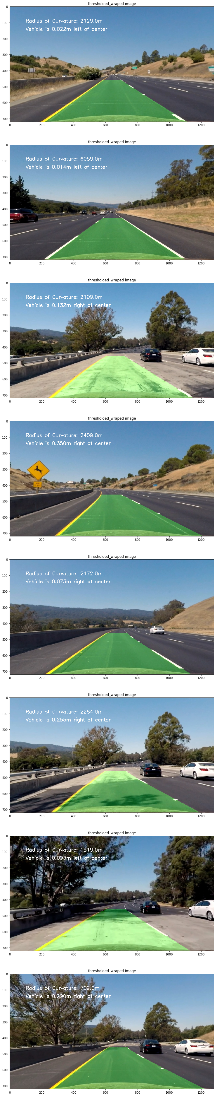
以下為測試圖片處理后結果:
以下為處理后測試視頻鏈接:
