1. 依據arch/arm/kernel/vmlinux.lds 生成linux內核源碼根目錄下的vmlinux,這個vmlinux屬於未壓縮,帶調試信息、符號表的最初的內核,大小約23MB;
命令:arm-linux-gnu-ld -o vmlinux -T arch/arm/kernel/vmlinux.lds
arch/arm/kernel/head.o
init/built-in.o
--start-group
arch/arm/mach-s3c2410/built-in.o
kernel/built-in.o
mm/built-in.o
fs/built-in.o
ipc/built-in.o
drivers/built-in.o
net/built-in.o
--end-group .tmp_kallsyms2.o
2. 將上面的vmlinux去除調試信息、注釋、符號表等內容,生成arch/arm/boot/Image,這是不帶多余信息的linux內核,Image的大小約3.2MB;
命令:arm-linux-gnu-objcopy -O binary -S vmlinux arch/arm/boot/Image
3.將 arch/arm/boot/Image 用gzip -9 壓縮生成arch/arm/boot/compressed/piggy.gz大小約1.5MB;
命令:gzip -f -9 < arch/arm/boot/compressed/../Image > arch/arm/boot/compressed/piggy.gz
4. 編譯arch/arm/boot/compressed/piggy.S 生成arch/arm/boot/compressed/piggy.o大小約1.5MB,這里實際上是將piggy.gz通過piggy.S編譯進piggy.o文件中。而piggy.S文件僅有6行,只是包含了文件piggy.gz;
命令:arm-linux-gnu-gcc -o arch/arm/boot/compressed/piggy.o arch/arm/boot/compressed/piggy.S
5. 依據arch/arm/boot/compressed/vmlinux.lds 將arch/arm/boot/compressed/目錄下的文件head.o 、piggy.o 、misc.o鏈接生成 arch/arm/boot/compressed/vmlinux,這個vmlinux是經過壓縮且含有自解壓代碼的內核,大小約1.5MB;
命令:arm-linux-gnu-ld zreladdr=0x30008000 params_phys=0x30000100 -T arch/arm/boot/compressed/vmlinux.lds arch/arm/boot/compressed/head.o arch/arm/boot/compressed/piggy.o arch/arm/boot/compressed/misc.o -o arch/arm/boot/compressed/vmlinux
6. 將arch/arm/boot/compressed/vmlinux去除調試信息、注釋、符號表等內容,生成arch/arm/boot/zImage大小約1.5MB;這已經是一個可以使用的linux內核映像文件了;
命令:arm-linux-gnu-objcopy -O binary -S arch/arm/boot/compressed/vmlinux arch/arm/boot/zImage
7. 將arch/arm/boot/zImage添加64Bytes的相關信息打包為arch/arm/boot/uImage大小約1.5MB;
命令: ./mkimage -A arm -O linux -T kernel -C none -a 0x30008000 -e 0x30008000 -n 'Linux-2.6.35.7' -d arch/arm/boot/zImage arch/arm/boot/uImage
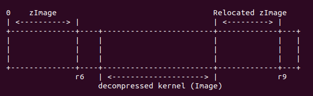
借用biscuitos的一張圖直觀的描述下壓縮內核生成過程:

二: 代碼分析
1. zImage 入口函數
zImage 初始化階段源碼位於 arch/arm/boot/compressed/ 目錄下。根據之前分析的原理可知, 壓縮之后的內核會添加 bootstrap 功能之后生成 vmlinux,再經過 OBJCOPY 工具處理生成 zImage。所以可以通過查看 vmlinux 的鏈接腳本確定 zImage 的入口地址。 zImage 使用 的鏈接腳本位於 arch/arm/boot/compressed/vmlinux.lds.S, 具體內容如下:
OUTPUT_ARCH(arm)
ENTRY(_start)
SECTIONS
{
  /DISCARD/ : {
    *(.ARM.exidx*)
    *(.ARM.extab*)
    /*
     * Discard any r/w data - this produces a link error if we have any,
     * which is required for PIC decompression.  Local data generates
     * GOTOFF relocations, which prevents it being relocated independently
     * of the text/got segments.
     */
    *(.data)
  }

  . = TEXT_START;
  _text = .;

  .text : {
    _start = .;
    *(.start)
    *(.text)
    *(.text.*)
    *(.fixup)
    *(.gnu.warning)
    *(.glue_7t)
    *(.glue_7)
  }
從鏈接腳本可以知道 vmlinux 鏈接過程,使用 ENTRY 關鍵字指定了 vmlinux 的入口地址, 也就是第一行運行的代碼,這里設置為 _start, 從上面可以看出 _start 位於 .text section 的首地址,所以這里鏈接腳本告訴開發者,vmlinux 運行的第一行代碼就是 vmlinux .text section 的第一行代碼。繼續查看鏈接腳本, .text section 的布局是所有目標文件的 .start section 位於 vmlinux .text section 的最前部,所以開發者只需找到目標文件 中函數 .start section 的文件即可。
由arch/arm/boot/compressed/Makefile可知,head.o第一個被鏈接進vmlinx, start段為heads中的start section
HEAD    = head.o
$(obj)/vmlinux: $(obj)/vmlinux.lds $(obj)/$(HEAD) $(obj)/piggy.o \
        $(addprefix $(obj)/, $(OBJS)) $(lib1funcs) $(ashldi3) \
        $(bswapsdi2) $(efi-obj-y) FORCE
    @$(check_for_multiple_zreladdr)
    $(call if_changed,ld)
    @$(check_for_bad_syms)
找到start開始的代碼如下:
        .section ".start", #alloc, #execinstr     //屬性是可分配和可執行的 /*
 * sort out different calling conventions
 */
        .align
        /*
         * Always enter in ARM state for CPUs that support the ARM ISA.
         * As of today (2014) that's exactly the members of the A and R
         * classes.
         */
 AR_CLASS(    .arm    )              //.align 偽指令和 .arm 偽指令告訴匯編器,這是一個使用 arm32 指令集並 要求對齊的 section
start:
        .type    start,#function
        .rept    7          @重復空操作7次
        __nop
        .endr
   ARM(        mov    r0, r0        )
   ARM(        b    1f        )    @跳轉到1處
 THUMB(        badr    r12, 1f        )
 THUMB(        bx    r12        )

        .word    _magic_sig    @ Magic numbers to help the loader  魔數0x016f2818是在bootloader中用於判斷zImage的存在
                            @而zImage的判別的magic number為0x016f2818,這個也是內核和bootloader約定好的。
        .word    _magic_start    @ absolute load/run zImage address  //用於指定 zImage 的加載和運行的絕對地址
        .word    _magic_end    @ zImage end address
        .word    0x04030201    @ endianness flag                    //表示字節序標志

 THUMB(        .thumb            )
1:        __EFI_HEADER                                             //指向 EFI 頭

 ARM_BE8(    setend    be        )    @ go BE8 if compiled for BE8
 AR_CLASS(    mrs    r9, cpsr    )
#ifdef CONFIG_ARM_VIRT_EXT
        bl    __hyp_stub_install    @ get into SVC mode, reversibly
#endif
        @//r1和r2中分別存放着由bootloader傳遞過來的architecture ID和指向標記列表的指針。
        mov    r7, r1            @ save architecture ID
        mov    r8, r2            @ save atags pointer

#ifndef CONFIG_CPU_V7M
        /*
         * Booting from Angel - need to enter SVC mode and disable
         * FIQs/IRQs (numeric definitions from angel arm.h source).
         * We only do this if we were in user mode on entry.
         */
        mrs    r2, cpsr        @ get current mode
        tst    r2, #3            @ not user?
        bne    not_angel
        mov    r0, #0x17        @ angel_SWIreason_EnterSVC
 ARM(        swi    0x123456    )    @ angel_SWI_ARM  angel_SWI_ARM //0x123456是arm指令集的半主機操作編號
 THUMB(        svc    0xab        )    @ angel_SWI_THUMB
not_angel:
        safe_svcmode_maskall r0    @進入svc模式
        msr    spsr_cxsf, r9        @ Save the CPU boot mode in
                        @ SPSR
#endif
接下來,head.S 將找到物理地址的起始地址,這個時候 MMU 是沒有打開的,這個時候是 忽略任何地址對齊和偏移。head.S 選擇最開始的 128MB 處作為對齊地址,然后將 zImage 放在這物理地址起始處,這 128MB 就是用來專門存放 zImage 鏡像的。具體 代碼如下:
#ifdef CONFIG_AUTO_ZRELADDR
        /*
         * Find the start of physical memory.  As we are executing
         * without the MMU on, we are in the physical address space.
         * We just need to get rid of any offset by aligning the
         * address.
         *
         * This alignment is a balance between the requirements of
         * different platforms - we have chosen 128MB to allow
         * platforms which align the start of their physical memory
         * to 128MB to use this feature, while allowing the zImage
         * to be placed within the first 128MB of memory on other
         * platforms.  Increasing the alignment means we place
         * stricter alignment requirements on the start of physical
         * memory, but relaxing it means that we break people who
         * are already placing their zImage in (eg) the top 64MB
         * of this range.
         */
        mov    r4, pc
        and    r4, r4, #0xf8000000
        /* Determine final kernel image address. */
        add    r4, r4, #TEXT_OFFSET
#else
        ldr    r4, =zreladdr
#endif
這段代碼主要用於計算內核的解壓地址,並將解壓地址存儲到 r4 寄存器中。 首先調用代碼 “mov, r4, pc”,將當前 CPU 執行的地址存儲到 r4 ,然后在將 0xf8000000 的值與 r4 相與達到對齊的作用,確保之后的內核解壓地址按 128M 對齊,然后將 r4 寄存器的 值加上 TEXT_OFFSET,TEXT_OFFSET 代表內核的解壓地址,這樣 r4 寄存器就存儲了內核的解壓 地址。TEXT_OFFSET 定義在 arch/arm/Makefile 中,如下:
# Text offset. This list is sorted numerically by address in order to
# provide a means to avoid/resolve conflicts in multi-arch kernels.
textofs-y    := 0x00008000
# We don't want the htc bootloader to corrupt kernel during resume
textofs-$(CONFIG_PM_H1940)      := 0x00108000
# SA1111 DMA bug: we don't want the kernel to live in precious DMA-able memory
ifeq ($(CONFIG_ARCH_SA1100),y)
textofs-$(CONFIG_SA1111) := 0x00208000
endif
textofs-$(CONFIG_ARCH_MSM8X60) := 0x00208000
textofs-$(CONFIG_ARCH_MSM8960) := 0x00208000
textofs-$(CONFIG_ARCH_AXXIA) := 0x00308000
# The byte offset of the kernel image in RAM from the start of RAM.
TEXT_OFFSET := $(textofs-y)
這里根據自己環境的芯片類型選擇ofset(:=表示覆蓋之前的賦值)。這里分析按照0x00008000進行計算。
接着執行如下代碼
        /*
         * Set up a page table only if it won't overwrite ourself.
         * That means r4 < pc || r4 - 16k page directory > &_end.
         * Given that r4 > &_end is most unfrequent, we add a rough
         * additional 1MB of room for a possible appended DTB.
         */
        mov    r0, pc
        cmp    r0, r4    //此操作影響狀態寄存器中的C狀態位.
        ldrcc    r0, LC0+32
        addcc    r0, r0, pc
        cmpcc    r4, r0
        orrcc    r4, r4, #1        @ remember we skipped cache_on
        blcs    cache_on  //如果pc>r4則直接執行這里
其中LC0定義如下
        .align    2
        .type    LC0, #object
LC0:        .word    LC0            @ r1
        .word    __bss_start        @ r2
        .word    _end            @ r3
        .word    _edata            @ r6
        .word    input_data_end - 4    @ r10 (inflated size location)
        .word    _got_start        @ r11
        .word    _got_end        @ ip
        .word    .L_user_stack_end    @ sp
        .word    _end - restart + 16384 + 1024*1024   //LC0+32位置,zImage 需要重定位的長度再加上 “16K + 1M” 的長度
        .size    LC0, . - LC0
這段代碼的主要任務就是確認 zImage 自己建立的頁表會不會被 zImage 鏡像的重定位給覆蓋掉。從原理可以知道,zImage 被加載到內存運行之后,會將自己重定位到新的物理地址運行,這就會出現要創建的頁表可能被 zImage 重定位之后覆蓋。zImage 鏡像如果不被自己給 覆蓋,需要滿足兩個條件中的任意一個:
r4 < PC

這種情況下,內核的解壓地址小於當前 PC 運行物理地址。
r4 - 16k page directory > &_end
這種情況下,內核的解壓地址大於 zImage 結束地址之后的 16KB。一般情況下解壓內核 的地址大於 zImage 的結束地址是不太尋常的。這種情況下需要添加 1MB 的空間與鏈接在 zImage 中的 DTB 隔開。
運行到這里,首先獲得 PC 寄存器的值,然后調用 “cmp r0, r4”, 從之前的代碼可知, r4 寄存器存儲着解壓內核的地址,這里執行這條命令的含義是,如果 r0 > r4,那么代表當前 PC 執行地址大於內核解壓地址,這種情況符合之前的討論,所以那么就執行 cache_on 宏; 如果 r0 < r4, 那么 zImage 的運行范圍包含了要解壓內核的地址,因此需要繼續進行檢測。 這里執行命令 “ldrcc r0, LC0+32”, 通過這個命令,將 LC0 偏移 32 個字節地址對應的內容 拷貝到 r0 寄存器。這里再加上 PC 的值,確保當前運行的代碼也不會被覆蓋。 接着執行命令 “cmpcc r4, r0”, 重新確定解壓內核的物理地址與 zImage 重定位的物理地址 是否存在重疊。如果存在,那么將 r4 寄存器的值加 1,以此標記 cache_on 被跳過;否則 執行 “blcs cache_on” 打開緩存。
cache_on代碼如下
/*
 * Turn on the cache.  We need to setup some page tables so that we
 * can have both the I and D caches on.
 *
 * We place the page tables 16k down from the kernel execution address,
 * and we hope that nothing else is using it.  If we're using it, we
 * will go pop!
 *
 * On entry,
 *  r4 = kernel execution address
 *  r7 = architecture number
 *  r8 = atags pointer
 * On exit,
 *  r0, r1, r2, r3, r9, r10, r12 corrupted
 * This routine must preserve:
 *  r4, r7, r8
 */
        .align    5
cache_on:    mov    r3, #8            @ cache_on function
        b    call_cache_fn
cache_on 用於打開 ARM 的 cache 功能,cache 包括 I-Cache (指令 cache) 和 D-cache (數據 cache)。為了正常使用 cache,需要建立一個頁表供 MMU 使用。zImage 會將這個頁表 放在真正內核開始執行地址之前的 16K 位置,希望這個地址不要被非法使用。在執行 cache_on 之前, r4 寄存器里存儲值內核解壓地址,這個地址也被成為正真內核開始執行的地址。r7 寄存器存儲這體系 相關的數據;r8 寄存器存儲着 uboot 傳遞給內核 ATAG 參數的地址。cache_on 使用偽指令 .align 指定了對齊方式為 5 字節對齊。由於 ARM 將所有家族芯片關於 cache 的操作都放在一個表里維護, 因此 armv7 的 cache 操作也在這個表內,並且 cache_on 操作在表中的偏移是 8,因此代碼 將立即數 8 存儲到 r3 寄存器,並跳轉到 call_cache_fn 出執行,代碼如下:
call_cache_fn:    adr    r12, proc_types
#ifdef CONFIG_CPU_CP15
        mrc    p15, 0, r9, c0, c0    @ get processor ID
#elif defined(CONFIG_CPU_V7M)
        /*
         * On v7-M the processor id is located in the V7M_SCB_CPUID
         * register, but as cache handling is IMPLEMENTATION DEFINED on
         * v7-M (if existant at all) we just return early here.
         * If V7M_SCB_CPUID were used the cpu ID functions (i.e.
         * __armv7_mmu_cache_{on,off,flush}) would be selected which
         * use cp15 registers that are not implemented on v7-M.
         */
        bx    lr
#else
        ldr    r9, =CONFIG_PROCESSOR_ID
#endif
1:        ldr    r1, [r12, #0]        @ get value
        ldr    r2, [r12, #4]        @ get mask
        eor    r1, r1, r9        @ (real ^ match)
        tst    r1, r2            @       & mask
 ARM(        addeq    pc, r12, r3        ) @ call cache function
 THUMB(        addeq    r12, r3            )
 THUMB(        moveq    pc, r12            ) @ call cache function
        add    r12, r12, #PROC_ENTRY_SIZE
        b    1b
本段代碼的主要任務就是 cache_on 表中找到 armv7 對應的 cache_on 操作。代碼首先使用 adr 偽指令獲得 proc_types 的地址,然后在 CONFIG_CPU_CPU15 宏啟用的情況下,armv7 這個宏啟用, 使用 mrc 指令,讀取了 CPU ID 寄存器。
將 ID 相關的信息存儲在 r9 寄存器里,然后使用 ldr 指令,從 proc_types 表里按順序取出每個 成員的第一個值和第二個值,分別存儲在 r1, r2 寄存器中。接着代碼將 r1 寄存器的值與 r9 寄存器 的值做異或運算,然后將結果存儲到 r1 寄存器,接着再調用 tst 命令,將 r1 寄存器與 r2 寄存器 按位與操作。如果結果為零,那么就執行 addeq 指令,將 pc 指向表中的位置;如果結果不為零, 那么調用 add 指令,將 r12 指向下一個表成員,調用 b 指令繼續循環。
表 proc_types 定義為一個 object 對象,其中包含了 armv7 對應的成員,cache_on 對應的入口 函數就是: __armv7_mmu_cache_on,結構如下:
/*
 * Table for cache operations.  This is basically:
 *   - CPU ID match
 *   - CPU ID mask
 *   - 'cache on' method instruction
 *   - 'cache off' method instruction
 *   - 'cache flush' method instruction
 *
 * We match an entry using: ((real_id ^ match) & mask) == 0
 *
 * Writethrough caches generally only need 'on' and 'off'
 * methods.  Writeback caches _must_ have the flush method
 * defined.
 */
        .align    2
        .type    proc_types,#object
proc_types:
        .word    0x41000000        @ old ARM ID
        .word    0xff00f000
        mov    pc, lr
 THUMB(        nop                )
        mov    pc, lr
 THUMB(        nop                )
        mov    pc, lr
 THUMB(        nop                )
.word 0x000f0000 @ new CPU Id
.word 0x000f0000
W(b) __armv7_mmu_cache_on
W(b) __armv7_mmu_cache_off
W(b) __armv7_mmu_cache_flush
__armv7_mmu_cache_on 函數首先將 lr 寄存器的值存儲到 r12 寄存器,然后判斷 CONFIG_MMU 宏是否啟用。在 armv7 里,這個宏是啟用的,所以執行宏限定的代碼。首先也是通過 mrc 指令讀取 ID_MMFR0 寄存器的值到 r11 寄存器中
其中, ID_MMFR0 的最低位用於指示當前 CPU 是支持 VMSA 還是 PMSA。VMSA 指的是 Virtual Memory System Architecture。PMSA 指的是 Protected Memory System Architecture。 兩種模式具有不同的內存管理策略,具體介紹開發者可以參考 ARMv7 Reference Manual。接着使用 tst 指令查看 r11 寄存器的最低 4 位的值,以此判斷目前 CPU 是 VMSA 模式還是 PMSA 模式。 如果 r11 寄存器的最低 4 bit 不為零,即 CPU 支持 VMSA 模式,那么代碼繼續執行帶 ne 條件 的指令。
__armv7_mmu_cache_on:
        mov    r12, lr
#ifdef CONFIG_MMU
        mrc    p15, 0, r11, c0, c1, 4    @ read ID_MMFR0
        tst    r11, #0xf        @ VMSA
        movne    r6, #CB_BITS | 0x02    @ !XN
        blne    __setup_mmu
CPU 支持 VMSA,將 CB_BITS 或上 0x2 的值存儲到 r6 寄存器,並將跳轉到 __setup_mmu 繼續執行
__setup_mmu:    sub     r3, r4, #16384          @ Page directory size
                bic     r3, r3, #0xff           @ Align the pointer
                bic     r3, r3, #0x3f00
__setup_mmu 的主要功能是建立一個臨時頁表,並打開 MMU,以此供解壓程序使用虛擬地址。正如 上面的代碼所示,此時 r4 寄存器指向真正內核運行的起始地址,那么就在這個地址前 16K 處開始 建立頁表,將頁表的起始地址存儲到 r3 寄存器,並使用 bic 指令對 r3 的地址做對齊。
所以頁表和內核的位置關系如下圖所示:

繼續執行__setup_mmu中如下代碼:
/*
 * Initialise the page tables, turning on the cacheable and bufferable
 * bits for the RAM area only.
 */
                mov     r0, r3
                mov     r9, r0, lsr #18
                mov     r9, r9, lsl #18         @ start of RAM
                add     r10, r9, #0x10000000    @ a reasonable RAM size
                mov     r1, #0x12               @ XN|U + section mapping
                orr     r1, r1, #3 << 10        @ AP=11
                add     r2, r3, #16384
代碼首先將 r3 寄存器的值存儲到 r0 寄存器,並通過對 r0 寄存器按 (1«18) 對齊,獲得 RAM 的起始地址,然后假設 RAM 的長度大概是 256M,並將 RAM 結束地址存放在 r10 寄存器中。這里 這樣做的目的是:該階段,內核采用一個臨時頁表,頁表按 1:1 映射物理地址與虛擬地址,通過計算 獲得 RAM 的長度,以此對能真實映射 RAM 的頁表項設置一種標志集;同理對不能映射物理地址的頁表 項設置另外一種標志集。接着將 0x12 的值和 (3 « 10) 值存儲到 r1 寄存器中。將 r3 寄存器 的值加上 16K 存放到 r2 寄存器,主要是為了防止寫頁表時越界。上面的左移 18 bit, 再右移 18 bit, 主要是按 1M 頁表進行對齊。
繼續執行如下代碼:
1:              cmp     r1, r9                  @ if virt > start of RAM
                cmphs   r10, r1                 @   && end of RAM > virt
                bic     r1, r1, #0x1c           @ clear XN|U + C + B
                orrlo   r1, r1, #0x10           @ Set XN|U for non-RAM
                orrhs   r1, r1, r6              @ set RAM section settings
                str     r1, [r0], #4            @ 1:1 mapping
                add     r1, r1, #1048576
                teq     r0, r2
                bne     1b
這段代碼的主要任務就是設置各個頁表項。有前面的代碼可以知道,r1 存儲着虛擬地址,並且從虛擬 地址 0 開始。r9 寄存器值存儲着物理起始地址。上面代碼的邏輯基本可以歸納為當虛擬地址不在 RAM 對於的物理地址上,那么執行 bic 指令將 r1 寄存器的 0x1c 對應的位清理,然后將 r1 與 0x10 做或運算,以此標記這類頁表;如果虛擬地址在 RAM 對於的物理地址上,那么執行 bic 指令將 r1 寄存器的 0x1c 對應的位清理,然后將 r6 對應的標志與 r1 相與。經過上面的處理之后調用 str 指令將 r1 的值寫入 r0 寄存器對應的內存里,然后將 r0 寄存器的值加上 4. 然后將 r1 寄存器 的值加上 1M,如果 r0 的值小於 r2, 那么跳轉到 1 處繼續循環寫頁表。通過上面分析,可以獲得 兩種頁表的表示分別是: 1) 0xc12 (不映射 RAM) 2)0xc0e (映射 RAM)。
/*
 * If ever we are running from Flash, then we surely want the cache
 * to be enabled also for our execution instance...  We map 2MB of it
 * so there is no map overlap problem for up to 1 MB compressed kernel.
 * If the execution is in RAM then we would only be duplicating the above.
 */
        orr    r1, r6, #0x04        @ ensure B is set for this
        orr    r1, r1, #3 << 10
        mov    r2, pc
        mov    r2, r2, lsr #20
        orr    r1, r1, r2, lsl #20
        add    r0, r3, r2, lsl #2
        str    r1, [r0], #4
        add    r1, r1, #1048576
        str    r1, [r0]
        mov    pc, lr
ENDPROC(__setup_mmu)
接下來這段代碼主要的目的就是為了區分系統是從 Flash 啟動,如果是,那么就將 RAM 對應的頁表 的前 2M 設置特殊的頁表標志。此時經過映射之后,r1 指向了虛擬地址 0,然后調用 orr 指令將 r1 寄存器存儲特定的標志。通過將 PC 的值傳入 r2 寄存器,並計算出 r2 對應的頁表中的偏移, 然后寫入 r1 中的值到頁表中,然后在將 r1 的值指向下 1M 地址空間,最后將 lr 的值傳遞給 pc 寄存器,那么函數至此返回。
接着返回 __setup_mmu 的調用點。執行如下代碼:
__armv7_mmu_cache_on:
                mov     r12, lr
#ifdef CONFIG_MMU
                mrc     p15, 0, r11, c0, c1, 4  @ read ID_MMFR0
                tst     r11, #0xf               @ VMSA
                movne   r6, #CB_BITS | 0x2      @ !XN
                blne    __setup_mmu
                mov     r0, #0
                mcr     p15, 0, r0, c7, c10, 4  @ drain write buffer
                tst     r11, #0xf               @ VMSA
                mcrne   p15, 0, r0, c8, c7, 0   @ flush I,D TLBs
#endif
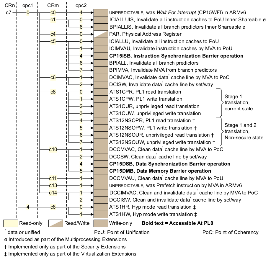
從 __setup_mmu 返回之后,代碼首先將 r0 寄存器設置為 0,然后調用 mcr 指令實現以此 DMB, 也就是內存屏障,保證這條指令之前所有內存訪問都必須完成。繼續使用 tst 指令確定當前模式是 VMSA 模式。如果是 VMSA 模式,那么就是調用 mcrne 指令,此時 CP15 調用情況如下圖:

因此此時選擇的是 TLBIALL 寄存器,向該寄存器寫入任何值都會影響刷 I-TLB 和 D-TLB. 這在 MMU 啟用之前是必要的。接下來執行的代碼是:
mrc    p15, 0, r0, c1, c0, 0    @ read control reg
        bic    r0, r0, #1 << 28    @ clear SCTLR.TRE
        orr    r0, r0, #0x5000        @ I-cache enable, RR cache replacement
        orr    r0, r0, #0x003c        @ write buffer
        bic    r0, r0, #2        @ A (no unaligned access fault)
        orr    r0, r0, #1 << 22    @ U (v6 unaligned access model)
                        @ (needed for ARM1176)
首先通過 mrc 指令讀取 CP15 寄存器,該寄存器的布局如下:

選擇 SCTLR 寄存器,其位布局圖如下:

接着就是對 SCTLR 寄存器特定位的操作,首先清楚掉 TRE 位,然后選中 I-cache enable, RR cache 替代算法,寫緩存,設置對齊方式,具體細節可以查看 ARMv7 Reference Manual。
接下來執行的代碼如下:
#ifdef CONFIG_MMU
                mrcne   p15, 0, r6, c2, c0, 2   @ read ttb control reg
                orrne   r0, r0, #1              @ MMU enable
                movne   r1, #0xfffffffd         @ domain 0 = client
                bic     r6, r6, #1 << 31        @ 32-bit translation system
                bic     r6, r6, #(7 << 0) | (1 << 4)    @ use only ttbr0
                mcrne   p15, 0, r3, c2, c0, 0   @ load page table pointer
                mcrne   p15, 0, r1, c3, c0, 0   @ load domain access control
                mcrne   p15, 0, r6, c2, c0, 2   @ load ttb control
#endif
接下來的代碼是設置 MMU 最重要的代碼,這段代碼主要任務就是設置頁表的基地址寄存器,並將該寄存器 的值指向了頁表的基地址。首先調用 mrcne 指令,代表了在 VMSA 模式下,讀取 TTB 控制器,對應 的 CP15 c2 寄存器如下:

選擇了 TTBCR 寄存器,對應的位圖如下:

繼續上面 r0 寄存器,設置了 r0 最地位,這里對應這 MMU enable 位,置位之后一旦寫入 SCTR 寄存器,那么 MMU 就可以使用了。domain 的訪問設置為 client. 對於 TTBCR 寄存器,將 31 bit 清理,以此支持 32 位的地址轉換,然后對 TTBCR 寄存器,清楚低 3 位和第 4 位,以此告訴頁表 只是用 TTBR0 作為頁表的基地址。接下來是將值寫到 CP15 對應的寄存器上,第一條指令是 “mcrne p15, 0, r3, c2, c0, 0”, 這條命令的作用是將頁表的基地址存儲到 TTBR0 寄存器, 從上面的代碼可以知道,r3 寄存器一直存儲着頁表的基地址。第二條指令是 “mcrne p15, 0, r1, c3, c0, 0”, 設置了 domain 的訪問域。第三條指令是 “mcrne p15, 0, r6, c2, c0, 2”, 告訴頁表控制器, 目前使用的頁表是 32 位裝換方式,並且只使用 TTBR0 寄存器作為頁表的基地址。
接下來執行的代碼是:
                mcr     p15, 0, r0, c7, c5, 4   @ ISB
                mcr     p15, 0, r0, c1, c0, 0   @ load control register
                mrc     p15, 0, r0, c1, c0, 0   @ and read it back
                mov     r0, #0
                mcr     p15, 0, r0, c7, c5, 4   @ ISB
                mov     pc, r12
運行到最后階段,將這前設置好的值寫入到對應的寄存器中。首先執行以此 ISB 指令,將流水線,內存 訪問操作全部 flush 一次。接着執行命令 “mcr p15, 0, r0, c1, c0, 0”, 將之前關於 MMU enable/I-cache/D-cache 等在 SCTR 控制器的配置全部寫入到 SCTR 寄存器中,寫入之后, 系統立即生效。至此 MMU 和 I-cache 和 D-cache 都能使用。這里再次調用 ISB 指令,將流水線 上的指令等同步到最新的配置。最后將 r12 的返回地址賦值給 pc,實現函數返回。
在啟用 MMU 之后,此時物理地址和虛擬地址按 1:1 映射。回到之前執行代碼的位置繼續執行如下 代碼:
restart:        adr     r0, LC0
                ldmia   r0, {r1, r2, r3, r6, r10, r11, r12}
                ldr     sp, [r0, #28]
這段代碼很簡單,就是 zImage 階段創建了一個簡單的表 LC0,然后將 LC0 表的內容分別賦值給指定 的寄存器。LC0 表用於存儲 zImage 鏈接階段各個重要段的偏移值,這里首先查看一下 LC0 表的內容:
                .align  2
                .type   LC0, #object
LC0:            .word   LC0                     @ r1
                .word   __bss_start             @ r2
                .word   _end                    @ r3
                .word   _edata                  @ r6
                .word   input_data_end - 4      @ r10 (inflated size location)
                .word   _got_start              @ r11
                .word   _got_end                @ ip
                .word   .L_user_stack_end       @ sp
                .word   _end - restart + 16384 + 1024*1024
                .size   LC0, . - LC0
從上面的定義可以知道:
1) LC0 + 0: LC0 在 zImage 中的偏移地址
2) LC0 + 4: BSS 段起始地址在 zImage 鏡像中的偏移地址
3) LC0 + 8: BSS 段結束地址在 zImage 鏡像中的偏移地址
4) LC0 + 12: 壓縮內核的長度在 zImage 鏡像中的偏移地址
5) LC0 + 16: zImage GOT 表起始地址在 zImage 鏡像中的偏移地址
6) LC0 + 20: zImage GOT 表結束的地址 zImage 鏡像中的偏移地址
7) LC0 + 24: zImage 堆棧的位置
8) LC0 + 28: zImage 重定位的長度
9) LC0 + 32: LC0 表長
因此執行命令 “ldmia r0, {r1, r2, r3, r6, r10, r11, r12}” 之后,這些值就被存儲到 指定寄存器里,並且調用命令 “ldr sp, [r0, #28]” 獲得堆棧的偏移地址。
經過上面的實踐之后,各個寄存器已經載入指定的值,接下來執行的代碼是:
/*
 * We might be running at a different address. We need
 * to fix up various pointers.
 */
sub     r0, r0, r1              @ caclculate the delta offset
add     r6, r6, r0              @ _edata
add     r10, r10, r0            @ inflated kernel size location
由於 LC0 表內的值有的是鏈接時相對於 zImage 鏡像的偏移值,此時開發者需要通過這些值 加載到內存之后對應的值,因此上面的代碼就是用於矯正 LC0 內的新值。從之前的代碼可以知道, r0 寄存器存儲的值是 LC0 表在內存中的地址,此時由於 MMU 已經啟用,因此 r0 的值代表 LC0 表的虛擬地址,r1 寄存器存儲着 LC0 相對於 zImage 鏡像的偏移值。因此命令 “sub r0, r0, r1” 可以計算 LC0 表的基礎偏移,然后表內各項的偏移都可以通過這個值 進行計算。
r10 寄存器經過矯正之后對應這內核原始大小,那么原始內核大小是如何被存放到 LC0 表里 呢?回答這個問題首先應該明確幾點:解壓后的內核就是之前所說的 Image, Image 有完整的 vmlinux 經過 OBJCOPY 命令生成的二進制文件,這個 Image 是可以直接在內存上運行的, 所以知道 Image 長度是一個至關重要的問題。那么下面介紹一下編譯系統 Kbuild 是如何 計算 Image 長度呢?
首先 Image 經過壓縮之后獲得壓縮內核 piggy_data,其使用的壓縮命令如下:
$(obj)/piggy_data: $(obj)/../Image FORCE
        $(call if_changed,$(compress-y))
這段代碼位於 arch/arm/boot/compressed/Makefile, 這段代碼就是 Image 壓縮生成 piggy_data 壓縮內核的過程,具體使用哪種壓縮方法,通過 compress-y 決定,其定義 也在同一個文件中,如下:
compress-$(CONFIG_KERNEL_GZIP) = gzip
compress-$(CONFIG_KERNEL_LZO)  = lzo
compress-$(CONFIG_KERNEL_LZMA) = lzma
compress-$(CONFIG_KERNEL_XZ)   = xzkern
compress-$(CONFIG_KERNEL_LZ4)  = lz4
從上面的定義可知,內核支持多種壓縮方式,其中以 gzip 為例,piggy_data 的壓縮命令是:
$(obj)/piggy_data: $(obj)/../Image FORCE
        $(call if_changed,gzip)
Kbuild 的命令庫里查看這個命令的具體過程,Kbuild 的命令庫位於源碼 scripts/Makefile.lib, gzip 命令如下:
quiet_cmd_gzip = GZIP    $@
      cmd_gzip = cat $(filter-out FORCE,$^) | gzip -n -f -9 > $@
所以可以看到 gizp 的執行過程,這里有個很重要的概念:壓縮工具無論進行何種壓縮算法, 會在壓縮文件的最后四個字節存儲原始文件的大小,並按大端的模式存儲。例如使用工具分別 查看 Image 的大小以及 piggy_data 的最后四個字節,如下:
$ ll arch/arm/boot/Image
-rwxrwxr-x 1 buddy buddy 11931944 4月   1 07:06 Image*

$ bless arch/arm/boot/compressed/piggy_data
EB 11 97 AB C6 BC B8 40 5D 87 38 5B 35 E6 05 45 6A EC 99 66 4F 5F
49 A3 3F 96 EB A4 1D 2B E9 1A BB 1B D7 B7 78 F5 80 26 4E 4E FF 0F
A1 10 18 DA 28 11 B6 00
通過上面的數據分析可到,piggy_data 的最后四個字節是 28 11 B6 00, 按小端調整之后的 值是 0x00B61128, 對應十進制值是 11931944, 數值正好對應 Image 的長度,因此上面的 推論是正確的。這是 piggy_data 的最后四字節存儲着 Image 的長度,根據原理可以知道 Kbuild 編譯系統將 piggy.S 匯編文件將 piggy_data 二進制文件封裝成一個匯編文件,並 鏈接成一個 ELF 文件,並在 piggy.S 中定義了兩個全局符號: “input_data” 和 “input_data_end”, 這兩個符號標記了 piggy.o 里 piggy_data 的起始偏移地址和 終止偏移地址。並在該目錄下的 vmlinux.lds.S 腳本里定義了 .piggydata section, section 內部也定義了一個變量 __piggy_size_addr, 這個變量正好指向了 piggy_data 最后 4 個字節。因此在 LC0+32 處定義為 “input_data_end - 4”, 因此以上數據都可以 知道壓縮內核解壓之后的長度。其他壓縮方法同理。接着執行如下命令:
/*
 * The kernel build system appends the size of the
 * decompressed kernel at the end of the compressed data
 * in little-endian form.
 */
ldrb    r9, [r10, #0]
ldrb    lr, [r10, #1]
orr     r9, r9, lr, lsl #8
ldrb    lr, [r10, #2]
ldrb    r10, [r10, #3]
orr     r9, r9, lr, lsl #16
orr     r9, r9, r10, lsl #24
通過上面的分析可以知道,r10 寄存里存儲 piggy_data 的最后面四個字節地址,這個地址 存儲着壓縮內核解壓之后的長度,也就是 Image 的長度,但是其長度在這四個字節里按大端 格式存儲,因此需要上面的代碼將大端數據讀出轉換為小端格式。代碼邏輯很簡單,就是使用 ldrb 指令從 r10 對應的地址上讀一個字節,然后調整字節序,最后壓縮內核解壓之后的長度 存儲到 r9 寄存器里。
獲得了 Image 長度的正確值后,接着繼續執行代碼:
#ifndef CONFIG_ZBOOT_ROM
                /* malloc space is above the relocated stack (64k max) */
                add     sp, sp, r0
                add     r10, sp, #0x10000
#endif
                mov     r5, #0                  @ init dtb size to 0
這里主要作用是分配 64K 的空間。首先矯正了堆棧的虛擬地址,並且將堆棧之后增加了 64K 空間 用於 malloc,將 malloc + stack + zImage 的長度存儲到 r10 寄存器中。然后將 r5 設置 為 0 供 DTB 使用,但是由於本實踐不支持 DTB APPEND 模式,因此接下來執行代碼如下:
/*
 * Check to see if we will overwrite ourselves.
 *   r4  = final kernel address (possibly with LSB set)
 *   r9  = size of decompressed image
 *   r10 = end of this image, including  bss/stack/malloc space if non XIP
 * We basically want:
 *   r4 - 16k page directory >= r10 -> OK
 *   r4 + image length <= address of wont_overwrite -> OK
 * Note: the possible LSB in r4 is harmless here.
 */
                add     r10, r10, #16384
                cmp     r4, r10
                bhs     wont_overwrite
                add     r10, r4, r9
                adr     r9, wont_overwrite
                cmp     r10, r9
                bls     wont_overwrite
這段代碼的主要任務是確定當前 zImage 運行的范圍會不會與內核解壓之后的地址范圍重合,如果 重合,那么 zImage 要做相應的調整,這里涉及到 zImage 重定位到一個新的地址繼續運行,這樣 zImage 和解壓內核相互影響。在執行代碼之前,r4 指向解壓內核的起始地址,r9 代表解壓 之后內核的長度,r10 寄存器代表當前 zImage 的長度(該長度也包含了 bss/stack/malloc) 的長度,因此需要做對比操作。那么在什么情況下不用重定位或重合呢,如下面幾種情況:
r4 - 16K >= r10
對於這種情況,內存分布如下:
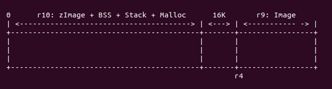
在這種情況下,zImage 運行的地址域與內核解壓之后的地址域是不重合的,所以 zImage 不需要重定位,直接在原始地址上直接運行。
r4 + image < wont_overwrite
對於這種情況,內存布局如下:
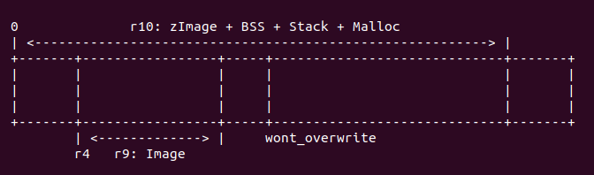
首先調用命令 “add r10, r10, #16384”, 將 r10 的長度再增加 16K,此時 r10 代表 zImage 長度加上 BSS/Stack/Malloc,再加上 16K 的長度,此時 r10 也可以表示 zImage 運行時完整的長度。接着調用 “cmp r4, r10” 命令,查看此時 zImage 的長度域與解壓內核 長度域之間的關系是否滿足 “r4 - 16K >= r10” 條件, 如果滿足,則執行 “bhs wont_overwrite”, 這樣 zImage 就不需要重定位;如果不滿足,那么繼續確認是否 滿足第二個條件,執行命令 “add r10, r4, r9”, 使 r10 寄存器存儲解壓內核的終止 物理地址,再調用命令 “adr r9, wont_overwrite” 獲得 zImage 中 wont_overwrite 的地址,最后執行命令 “cmp r10, r9”, 如果 r10 小於 r9, 那么滿足第二個條件,則執行 “bls wont_overwrite”, zImage 不需要重定位;反之 zImage 需要重定位。
zImage 與解壓之后的內核存在重疊時,zImage 需要重定位,它們 之間的關系如下:
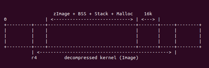
經過上面代碼執行,r9 寄存器存儲着 wont_overwrite 的地址, r10 寄存器存儲着解壓之后 內核的終止地址。接下來運行代碼:
/*
 * Relocate ourselves past the end of the decompressed kernel.
 *   r6  = _edata
 *   r10 = end of the decompressed kernel
 * Because we always copy ahead, we need to do it from the end and go
 * backward in case the source and destination overlap.
 */
                /*
                 * Bump to the next 256-byte boundary with the size of
                 * the relocation code added. This avoids overwriting
                 * ourself when the offset is small.
                 */
                add     r10, r10, #((reloc_code_end - restart + 256) & ~255)
                bic     r10, r10, #255

                /* Get start of code we want to copy and align it down. */
                adr     r5, restart
                bic     r5, r5, #31
此時 r10 寄存器存儲着解壓之后內核的終止地址。”((reloc_code_end - restart + 256) & ~255)” 表示了 head.S 中 reloc_code_end 的長度,並按 256 字節對齊,運行命令之后,r10 寄存器 存儲了解壓之后內核的終止地址再加上 head.s 重定位代碼的長度。並將 head.S 中 restart 的地址存儲在 r5 寄存器中,並按 32 字節對齊。接下來執行代碼:
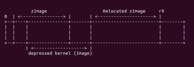
                sub     r9, r6, r5              @ size to copy
                add     r9, r9, #31             @ rounded up to a multiple
                bic     r9, r9, #31             @ ... of 32 bytes
                add     r6, r9, r5
                add     r9, r9, r10
此處,r6 寄存器表示 zImage 不帶 BSS 段的長度,即原始 zImage 的長度。這里調用命令 “sub r9, r6, r5”,將 zImage 的長度減去需要 head.S 中需要重定位的長度之后的值, 存儲到 r9 寄存器中,並將 r9 寄存器按 32 字節對齊。接着將 r9 寄存器的值存儲到 r6 寄存器中,這樣 r6 寄存器存儲着 zImage 減去 head.S 中重定位長度之后的終止地址。接着執行命令 “add r9, r9, r10”, 通過這個命令,r9 存儲了 zImage 重定位之后的結束物理地址, 他們之間關系如下圖:
接下來執行代碼:
1:              ldmdb   r6!, {r0 - r3, r10 - r12, lr}
                cmp     r6, r5
                stmdb   r9!, {r0 - r3, r10 - r12, lr}
                bhi     1b

                /* Preserve offset to relocated code. */
                sub     r6, r9, r6
這段代碼的主要任務就是搬運 zImage 到重定位的位置,搬運的內容不包括 zImage 的 BSS/ Stack/Malloc 區域。此時 r6 寄存器存儲着 zImage 的減去 head.S 重定位段之后的結束地址。 r9 寄存器存儲着解壓之后的內核終止地址加上 zImage 重定位的地址。此時內存布局如下:
這里使用 ldmdb 從 r6 對應的 zImage 的末尾往重定位 zImage 的末尾拷貝數據,這里 也就是搬運 zImage 到新的地址。ldmdb 一直循環知道 r6 的地址與 r5 對應的地址重合, 方才停止循環。
接下來執行的代碼如下:
#ifndef CONFIG_ZBOOT_ROM
                /* cache_clean_flush may use the satck, so relocated it */
                add     sp, sp, r6
#endif
並未定義 CONFIG_ZBOOT_ROM 宏情況下,由於接下來要執行 cache_clean_flush 需要使用 堆棧,所以將堆棧指向一個合適的位置,這里將堆棧加上 r6 寄存器的值。接下來調用 cache_clean_flush. 具體代碼如下:
/*
 * Clean and flush the cache to maintain consistency
 *
 * On exit,
 *  r1, r2, r3, r9, r10, r11, r12 corrupted
 * This routine must preserve:
 *  r4, r6, r7, r8
 */
                .align  5
cache_clean_flush:
                mov     r3, #16
                b       call_cache_fn
cache_clean_flush 的定義很簡單,與 cache_on 一樣的機制,都是在 CACHE 表中找到 __armv7_mmu_cache_flush 的入口,具體查找過程,查看前面關於 call_cache_fn 源碼解析, 通過 call_cache_fn 之后,會定位到 __armv7_mmu_cache_flush 處,代碼如下:
__armv7_mmu_cache_flush:
                tst     r4, #1
                bne     iflush
                mrc     p15, 0, r10, c0, c1, 5  @ read ID_MMFR1
                tst     r10, #0xf << 16         @ hierarchical cache (ARMv7)
                mov     r10, #0
                beq     hierarchical
                mcr     p15, 0, r10, c7, c14, 0 @ clean+invalidate D
                b       iflush
首先檢查 r4 寄存器的最低位是否置位,從前面的代碼可以知道,MMU 打開的情況下,r4 最低位清零; 如果 MMU 未啟用,那么 r4 最低位置位。由之前的分析可知,此處 MMU 已經啟用,所以 tst 的結果 未零,那么 “bne iflush” 命令將不被執行。接下來執行的代碼是: “mrc p15, 0, r10, c0, c1, 5”, 此時 CP15 C0 寄存器的布局如下:

通過上面的代碼選中了 ID_MMFR1 寄存器,該寄存器用於指定當前 CACHE 的類型,其位圖如下:
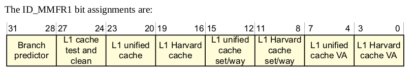
接着調用 tst 命令查看 ID_MMFR1 寄存器的 [19:16] 域,該域表示:
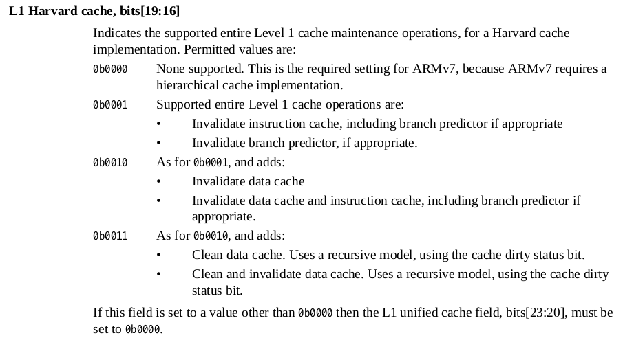
有上面的定義可知,該域用於指示 L1 cache 的維護操作。但在 armv7 中,這是不需要的,因此 tst 的結果等於 0,那么代碼接下來跳轉到 hierarchical 處繼續執行。
跳轉到 hierarchical 處繼續執行,由於 armv7 的 L1 cache 按分層管理,要給 cache 進行 flush 操作,首先要了解一下 cache 的基礎知識, 這里只介紹必要的知識,更多 cache 知識請查看:
L1 cache
在 ARMv7 中,cache 分為了指令 cache (I-Cache) 和數據 cache (D-cache), cache 是 用來加速內存訪問,其邏輯結構如下圖:
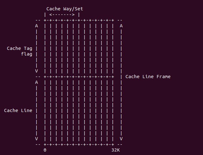
cache 的最小數據單位是 cache line, cache line 的長度成為 cache size;為了標記每個 cache line,使用的標記叫 cache tag, cache tag、cache line 與一些標志信息組成一個 cache line frame; 多個 cache line frame 組成一個 cache set;cache 被分成多個 cache set,每個 cache set 含有的 cache line 數成為 cache way.
在 armv7 中要 flush D-cache 按如下邏輯:
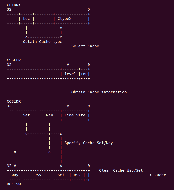
在 armv7 中,首先從 CLIDR 寄存器中讀取 LoC 域對應的 Ctype,從中找到 D-cache, 然后 在 CSSELR 寄存器寫入 D-cache 的 level 信息之后,CCSIDR 寄存器就指向了所要查找 cache 的信息,這些信息存儲在 CCSIDR 寄存器中,從這個寄存器中可以獲得當前 CACHE 的 cache line 數值,cache Set/Way 的值,通過這些值可以計算出需要 flush 的長度,最后將要清楚的值寫入 到 DCCISW 寄存器中,這樣該 level 的 cache 就被 flush 完了,接着遍歷 flush 下一級 cache。 因此 CACHE 的 flush 邏輯就是這樣。接下來通過代碼分析具體過程:
hierarchical:
                mcr     p15, 0, r10, c7, c10, 5 @ DMB
                stmfd   sp!, {r0-r7, r9-r11}
                mrc     p15, 1, r0, c0, c0, 1   @ read clidr
                ands    r3, r0, #0x7000000      @ extract loc from clidr
                mov     r3, r3, lsr #23         @ left align loc bit field
                beq     finished                @ if loc is 0, then no need to c
                mov     r10, #0                 @ start clean at cache level 0
首先做一次 DMB 內存屏蔽操作,將之前的內存訪問都同步。然后使用 stmfd 指令保存指定的寄存器, 接着調用 mrc 寄存器讀取 CP15 C0 寄存器,選擇如下:
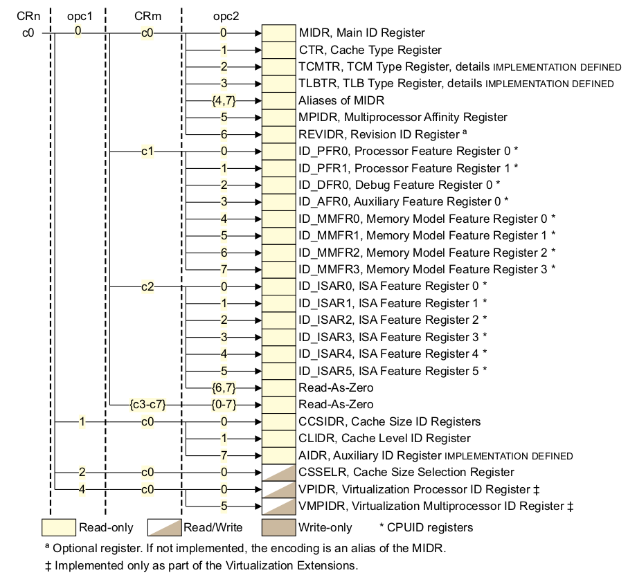
通過上面選中了 CLIDR 寄存器,該寄存器的布局如下圖:
然后執行代碼 “ands r3, r0, #0x7000000”, 以此讀取 CLIDR [26:24] 域,這個域用於 LoC (Level of Coherence for the cache hierarchy). 這個域用於指定一致性數據 cache 所在的 cache Level,然后通過 “mov r3, r3, lsr #23” 獲得 cache level 的具體 數值。如果該值為 0,那么代表沒有對應的 cache,直接跳轉到 finished 處;如果該值為 0, 那么代碼存在對應需要 flush 的 cache,那么繼續執行下面的代碼不跳轉。
loop1:
                add     r2, r10, r10, lsr #1    @ work out 3x current cache leve
                mov     r1, r0, lsr r2          @ extract cache type bits from c
                and     r1, r1, #7              @ mask of the bits for current c
                cmp     r1, #2                  @ see what cache we have at this
                blt     skip                    @ skip if no cache, or just i-ca
                mcr     p15, 2, r10, c0, c0, 0  @ select current cache level in
                mcr     p15, 0, r10, c7, c5, 4  @ isb to sych the new cssr&csidr
                mcr     p15, 1, r1, c0, c0, 0   @ read the new csidr
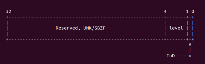
由於在 armv7 中 LoC cache 采用分級模式,所以在 flush cache 的時候,需要從 ctype0 開始 flush,每個 cache ctype 之間相差 3,所以這里使用 “add r2, r10, r10, lsr #1” 達到遍歷下一個 cache 的作用。接着就是對 ctypes 對應的值進行對比,這個值從手冊中可以 知道:1) 當該值為 0, 代表沒有 cache. 2) 該值為 1 代表指令 cache。 3) 該值為 2 代表數據 cache。4) 該值為 3 代表指令和數據分離的 cache。 5) 該值為 4 代表 Unified cache。 6) 其他值為 Reserved。如果此時 “cmp r1, #2” 的值小於 2,那么就代表這個 cache 是一個指令 cache 或者沒有 cache。如果 r1 寄存器的值小於 2 那么直接跳轉到 skip 處繼續執行,如果大於等於 2,那么繼續往下執行。接着如果是數據 cache,那么調用命令 “mcr p15, 2, r10, c0, c0, 0”, 此時 CP15 C0 的布局如下:
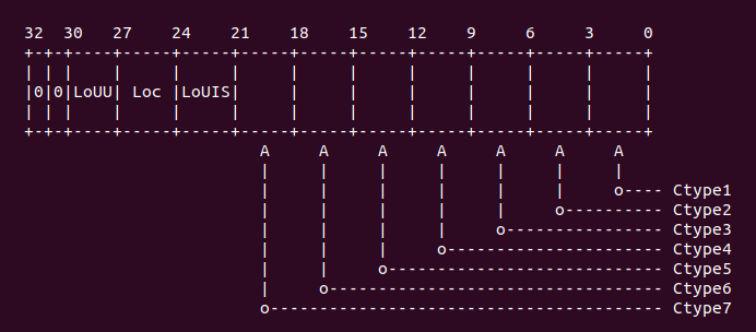
選中的寄存器是 CSSELR 寄存器,其內存布局如下:
這里用於選擇 Cache 的級數,在 armv7 中,只要在 CSSELR 寄存器的 Level 域中選中了 cache Level,那么 CSIDR 寄存器就反應被選中 cache 相關信息。為了是 CSSELR 寫入有效, 這里調用了內存屏蔽指令 ISB,執行完 ISB 之后,CSIDR 寄存器的值就是反應 CSSELR 選中 的結果,CSSELR 的內存布局如下:
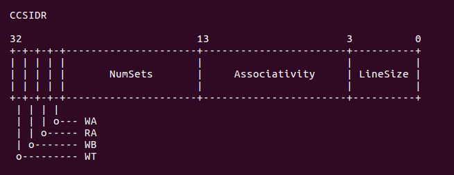
正如上圖所示,CSIDR 寄存器包含了當前 cache 的 Set 域,Way 域,以及 line size 域。
開發者可以在上面代碼中加入適當的斷點,然后使用 GDB 進行調試,調試情況如下:
(gdb) b BS_debug
Breakpoint 1 at 0x600102a4: file arch/arm/boot/compressed/head.S, line 341.
(gdb) c
Continuing.

Breakpoint 1, BS_debug () at arch/arm/boot/compressed/head.S:341
341            add    r2, r10, r10, lsr #1    @ work out 3x current cache level
(gdb) n
342            mov    r1, r0, lsr r2        @ extract cache type bits from clidr
(gdb) info reg r10
r10            0x0                 0
(gdb) info reg r2
r2             0x0                 0
(gdb) n
343            and    r1, r1, #7        @ mask of the bits for current cache only
(gdb) info reg r1
r1             0x9000003           150994947
(gdb) n
344            cmp    r1, #2            @ see what cache we have at this level
(gdb) info reg r1
r1             0x3                 3
(gdb) n
345            blt    skip            @ skip if no cache, or just i-cache
(gdb) n
346            mcr    p15, 2, r10, c0, c0, 0    @ select current cache level in cssr
(gdb) n
347            mcr    p15, 0, r10, c7, c5, 4    @ isb to sych the new cssr&csidr
(gdb) info reg r10
r10            0x0                 0
(gdb) n
348            mrc    p15, 1, r1, c0, c0, 0    @ read the new csidr
(gdb) n
349            and    r2, r1, #7        @ extract the length of the cache lines
(gdb) info reg r1
r1             0xe00fe019          -535830503
(gdb)
從上面的實踐可以看出,LoC 所使用的 cache 是一個數據 cache,對應的 Ctype1,並且 Ctype0 的 cache 為 0x3, 將該值寫入到 CSIDR 寄存器,就獲得 Ctype1 對應的 cache 長度信息。從 r1 讀入的值為 0xe00fe019, 從這個數值中可以知道 Cache 的 set 數為 (0x3F + 1), 也就是該 cache 包含了 128 個 set。每個 set 包含的 cache line 數 (0x3 + 1), 那么該 cache 是 4 way。cache line size 是 8 字節。接下來執行的 代碼是:
                and     r2, r1, #7              @ extract the length of the cache lines
                add     r2, r2, #4              @ add 4 (line length offset)
                ldr     r4, =0x3ff
                ands    r4, r4, r1, lsr #3      @ find maximum number on the way size
                clz     r5, r4                  @ find bit position of way size increment
                ldr     r7, =0x7fff
                ands    r7, r7, r1, lsr #13     @ extract max number of the index size
從之前的分析可以知道,r1 寄存器里面存儲着當前 cache 長度相關的信息,首先使用 “and r2, r1, #7” 獲得 cache line 的長度。然后調用 “add r2, r2, #4”,這條命令的 作用是為了后面 cache flush 特定寄存器寫信息的特殊格式要求,可以參看后面 flush 操作。 接着將常量 0x3ff 賦值給 r4, 然后執行命令 “ands r4, r4, r1, lsr #3”,通過這條 命令讀出 cache way 的信息,接着調用 “clz r5, r4” 也是為了拼湊一個格式化數據。同理, 將常量 0x7fff 賦值給 r7,然后獲得 cache 的 set 信息。接下來執行的代碼如下:
loop2:
                mov     r9, r4                  @ create working copy of max way size
loop3:
 ARM(           orr     r11, r10, r9, lsl r5    ) @ factor way and cache number into r11
 ARM(           orr     r11, r11, r7, lsl r2    ) @ factor index number into r11
                mcr     p15, 0, r11, c7, c14, 2 @ clean & invalidate by set/way
                subs    r9, r9, #1              @ decrement the way
                bge     loop3
                subs    r7, r7, #1              @ decrement the index
                bge     loop2
skip:
                add     r10, r10, #2            @ increment cache number
                cmp     r3, r10
                bgt     loop1
這段代碼就是按 set/way 方式 flush cache,這講解代碼之前,先了解 cache flush 的 方法,armv7 中采用 set/way 方式管理 cache。通過之前 cache 基本原理可以知道,每個 cache set 包含了 way 個 cache line,而 cache 被均分成多個 cache set。因此可以將 cache set 理解為行,cache way 理解為列,所以刷新的時候按行-列的模式刷,因此這里 的代碼就是用於實現將所有 set 和 way 都 flush。另外,armv7 中,往特定寄存器寫入 set/way 信息就可以刷新指定的 set/way cache, 這個寄存器就是 DCCISW 寄存器,這個 寄存器的位圖如下:
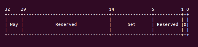
從上圖可以知道,要刷新特定的 cache line,那么需要往 DCCISW 寄存器內寫入 Way 和 Set 的信息。因此在分析之前的代碼,為什么 line size 的值要加上 4,以及 way 的值要這么 處理也就知道了,就是為了制作出一個符合 DCCISW 格式的數據。因此上面的代碼分析如下: 首先調用 “mov r9, r4”,為了進行 set 的遍歷,接着 “orr r11, r10, r9, lsl r5” 和 “orr r11, r11, r7, lsl r2” 命令也是為了構建 DCCISW 格式化數據,准備好數據之后, 就將數據寫入到 DCCISW 寄存器里面,使用的命令是 “mcr p15, 0, r11, c7, c14, 2”. 接下來的代碼就是遍歷所有的 set 以及 set 里面的所有 way,通過上面的操作,當前 cache 的所有 set/way 就被 flush 完畢。最后到達 skip 處,如果當前 cache flush 完畢, 那么跳轉到 loop1 采用同樣的方式遍歷下一個 cache。
接下來執行的代碼是:
finished:
                ldmfd   sp!, {r0-r7, r9-r11}
                mov     r10, #0                 @ switch back to cache level 0
                mcr     p15, 2, r10, c0, c0, 0  @ select current cache level in cssr
iflush:
                mcr     p15, 0, r10, c7, c10, 4 @ DSB
                mcr     p15, 0, r10, c7, c5, 0  @ invalidate I+BTB
                mcr     p15, 0, r10, c7, c10, 4 @ DSB
                mcr     p15, 0, r10, c7, c5, 4  @ ISB
                mov     pc, lr
cache flush 完畢之后,就做最后的收尾工作,將期間使用過的寄存器都恢復原值,然后 將當前 cache 設置為 0。然后刷新 I-cache。首先調用 DSB 內存屏障,將之訪問全部落盤, 然后調用 “mcr p15, 0, r10, c7, c5, 0”, 此時 CP15 C7 的布局如下:
通過上面的命令選中了寄存器:ICIALLU, 向該寄存器寫入任意值就會讓 I-cache 無效。 接着調用兩條內存屏障指令 DSB 和 ISB,讓所有改變都生效。最后將 lr 賦值給 pc,實現 調用返回。支持 armv7 的 flush 操作已經全部完成。
代碼繼續執行如下:
                badr    r0, restart
                add     r0, r0, r6
                mov     pc, r0
首先獲得 restart 的地址,存儲到 r0 寄存器內,然后將 r0 寄存器的值加上 r6 偏移值, 以此計算出 restart 重定位之后的地址,最后將該值賦值給 pc,然后 CPU 就跳轉到 restart 重定位處繼續執行。