opencv-6-圖像繪制與opencv Line 函數剖析
開始之前
越到后面, 寫的越慢, 之前還抽空去看了下 學堂在線那篇文章提供的方法, 博客第一個人評論的我, 想想還是要給人家一個交代的, 就想着找到一個方法進行下載, 但是嘗試了 還沒找到, 估計我要花時間自己寫一個了, 不是很難, 但是 就是要花時間, 安排到日程上了, 應該會有結果的, 到時候再寫博文記錄.
之前都是空的, 寫起來很快, 后面的話我還要去寫具體的代碼實現, 爭取都能夠復現出來, 這樣更有實際意義, 所以接下來可能更新的更慢了, 不過應該不會斷, 我計划的很長, 但是我想 至少寫夠20篇吧, 加油.
在這篇文章以及后續的文章中,我們都會 說明一些代碼出現的地方, 頭文件對應的 opencv 庫引用目錄 include 文件夾下面的文件 源文件則是 opencv 4.3.0 下的 Source 文件夾里面的文件
同樣的, 文件的后面使用 :xx 標識, 在文件的xx 行的地方
頭文件
opencv2/opencv.hpp:100在 opencv.hpp 第100 行開始的地方
源文件modules/imgproc/src/drawing.cpp:1000則是在 1000 行的地方
目錄
正文
在上一篇中, 我們能夠進行像素點的操作了, 那么, 很明顯的一個問題, 我能不能在圖像上畫一條線呢, 或者在圖像上自己用鼠標繪制呢, 當然可以, opencv 提供了這些功能,
在opencv 的文檔中 Basic Drawing, 基礎繪圖章節, 有相關的例程,
我們在之前的文章中提到了 opencv 座標系的問題
- 以左上角為起始點
- 橫向為x, 縱向為y
- 使用 at(rows,cols) 確定座標值 對應的是 (行,列)
- 使用 point(x,y) 定位, 使用的是 (列, 行)
這兩個定位是不一樣的 ,所一定要注意, opencv 在 繪制圖形的時候 使用的是 Point 來進行的定位, 我們可以使用 cv::Point p = cv::Point(20,30) 直接初始化, 或者使用 cv::Point p; p.x = 20,p.y=30; 初始化后進行賦值操作.
在圖像上繪制標准圖形
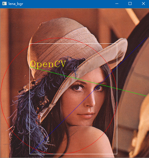
我們還以 lena 為例, 在圖片上繪制 以 (x,y) 座標的圖形
- 直線: 起點(100,200) - 終點(500,300) 綠色
- 直線: 起點 (100,500) - 終點(500,100) 藍色
- 圓: 圓心 (200,300) 半徑 200 紅色
- 矩形: 左上角點 (100,120) 右下角點(400,450); 白色
- 文字: 起始點: (100,200), 文字: OpenCV
- ....
在我們繪制之前, 我們要說明一個函數 cv::Scalar 是opencv 的顏色函數, 按照 BGR 的順序傳入三個參數, 用於指名繪制圖形的顏色
note: 實際上是 4個參數, 一般我們不使用最后一個參數即可[1]
編碼實現
我們根據上面給出的順序 依次 編寫代碼, 將圖形繪制到 lena 圖的上面,
我們可以得到這樣的程序, 就是一條一條的寫, 我們只需要調用 相應的opencv 函數就能繪制了,
#include <opencv2/opencv.hpp>
int main(int argc, char *argv[]) {
    //QApplication a(argc, argv);
    //MainWindow w;
    //w.show();
    // 設置 要顯示的圖像路徑
    std::string img_lena = "./TestImages/lena.png";

    // 讀取兩幅彩色圖像 512*512
    cv::Mat lena_bgr = cv::imread(img_lena);
    // 聲明結果圖像 1020*1020
    cv::Mat res_bgr = cv::Mat::zeros(cv::Size(512,512), CV_8UC3);

    // 繪制基本圖形
    cv::line(lena_bgr, cv::Point(100, 200), cv::Point(500, 300), cv::Scalar(0, 255, 0));
    cv::line(lena_bgr, cv::Point(100, 500), cv::Point(500, 100), cv::Scalar(255, 0, 0));
    cv::circle(lena_bgr, cv::Point(200, 300), 200, cv::Scalar(0, 0, 255));
    cv::rectangle(lena_bgr, cv::Rect(cv::Point(100, 120), cv::Point(400, 500)), cv::Scalar(255, 255, 255));

    cv::putText(lena_bgr, "OpenCV", cv::Point(100, 200), cv::FONT_HERSHEY_COMPLEX,1.0, cv::Scalar(0, 255, 255));

    cv::imshow("lena_bgr",lena_bgr);

    cv::waitKey(0);

    return 0;
    // return a.exec();
}
最終我們運行之后 ,便能夠得到這樣的一副圖像, 很簡單, 具體的參數部分自己選擇就好, 這里只是給出一個示例,

line 函數 源碼分析剖析
其實opencv 還能繪制其他的圖形, 太多了, 可以在Drawing Functions頁面去查看, 基本沒啥用, 很多時候是需要了自己造個輪子就行了, 不查文檔我都不知道能繪制這么多
只需要知道直線, 圓, 矩形怎么繪制的就行了, 多了也用不到
后續的部分 主要是 opencv 怎么去實現的 line 函數了, 涉及到比較基礎的, 看不看不影響你的使用, 不想看的就關閉即可..
源碼解析
我們以 繪制直線為例, 這個簡單, 我們使用了 cv::line 就繪制出來了一條直線
void cv::line	(	InputOutputArray 	img,
					Point 	pt1,
					Point 	pt2,
					const Scalar & 	color,
					int 	thickness = 1,
					int 	lineType = LINE_8,
					int 	shift = 0
)
各個參數意義其實名稱還是能夠 看出來的
- img: 輸入輸出圖像, 直接在這個圖像上繪制
- pt1: 起始點 (x,y) 座標
- pt2: 終止點 (x,y) 座標
- color: Scalar 參數生成的顏色
- *thickness: 直線寬度
- *lineType: 繪制的線的形式 4鄰域 8鄰域等
- *shift: 精度, 點座標中的小數點等級(第一次看到這個參數, 暫時不管他什么意思)
一般我們只需要前面的四個參數就行了, 一般就是我們程序中的 cv::line(lena_bgr, cv::Point(100, 200), cv::Point(500, 300), cv::Scalar(0, 255, 0));
座標顏色我們都說過了, 那我們去看下 他的源碼:
在 modules\imgproc\srcdrawing.cpp:1772 中, 我們能夠看到 直線的繪制函數,
void line( InputOutputArray _img, Point pt1, Point pt2, const Scalar& color, int thickness, int line_type, int shift ) {
    CV_INSTRUMENT_REGION();

    Mat img = _img.getMat();

    if( line_type == CV_AA && img.depth() != CV_8U )
        line_type = 8;

    CV_Assert( 0 < thickness && thickness <= MAX_THICKNESS );
    CV_Assert( 0 <= shift && shift <= XY_SHIFT );

    double buf[4];
    scalarToRawData( color, buf, img.type(), 0 );
    ThickLine( img, pt1, pt2, buf, thickness, line_type, 3, shift );
}
這個只是一個封裝, 將顏色分成一個double 數組, 然后 調用了一個新的函數 ThickLine
這里 實際上 這里的scalarToRawData 函數也是根據圖像的通道進行調用了, scalarToRawData_ 的函數, 將顏色結構體的四個值分別存入數組中, 也為了兼容以前的版本, 所以采用的這種接口.
template <typename T> static inline void scalarToRawData_(const Scalar& s, T * const buf, const int cn, const int unroll_to) {
    int i = 0;
    for(; i < cn; i++)
        buf[i] = saturate_cast<T>(s.val[i]);
    for(; i < unroll_to; i++)
        buf[i] = buf[i-cn];
}
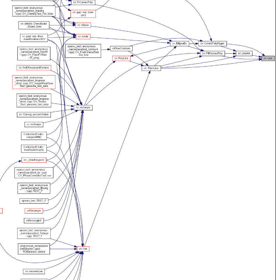
去看了下 opencv 的矩形 rectancle 函數是實際上是基於 polyline 多邊形繪制, 而它則是基於 ThickLine的, opencv 的函數都是這樣基於最簡單的元素來實現的, 所以我們繼續看這個實現就好
感覺線形狀的繪制最終都是調用的這個, 那我們去看下具體的實現.

在文件 modules\imgproc\src\drawing.cpp:1602 是這個函數的實現,
static void ThickLine( Mat& img, Point2l p0, Point2l p1, const void* color, int thickness, int line_type, int flags, int shift ) {
    static const double INV_XY_ONE = 1./XY_ONE;

    p0.x <<= XY_SHIFT - shift;
    p0.y <<= XY_SHIFT - shift;
    p1.x <<= XY_SHIFT - shift;
    p1.y <<= XY_SHIFT - shift;

    if( thickness <= 1 )
    {
        if( line_type < CV_AA )
        {
            if( line_type == 1 || line_type == 4 || shift == 0 )
            {
                p0.x = (p0.x + (XY_ONE>>1)) >> XY_SHIFT;
                p0.y = (p0.y + (XY_ONE>>1)) >> XY_SHIFT;
                p1.x = (p1.x + (XY_ONE>>1)) >> XY_SHIFT;
                p1.y = (p1.y + (XY_ONE>>1)) >> XY_SHIFT;
                Line( img, p0, p1, color, line_type );
            }
            else
                Line2( img, p0, p1, color );
        }
        else
            LineAA( img, p0, p1, color );
    }
    else
    {
        Point2l pt[4], dp = Point2l(0,0);
        double dx = (p0.x - p1.x)*INV_XY_ONE, dy = (p1.y - p0.y)*INV_XY_ONE;
        double r = dx * dx + dy * dy;
        int i, oddThickness = thickness & 1;
        thickness <<= XY_SHIFT - 1;

        if( fabs(r) > DBL_EPSILON )
        {
            r = (thickness + oddThickness*XY_ONE*0.5)/std::sqrt(r);
            dp.x = cvRound( dy * r );
            dp.y = cvRound( dx * r );

            pt[0].x = p0.x + dp.x;
            pt[0].y = p0.y + dp.y;
            pt[1].x = p0.x - dp.x;
            pt[1].y = p0.y - dp.y;
            pt[2].x = p1.x - dp.x;
            pt[2].y = p1.y - dp.y;
            pt[3].x = p1.x + dp.x;
            pt[3].y = p1.y + dp.y;

            FillConvexPoly( img, pt, 4, color, line_type, XY_SHIFT );
        }

        for( i = 0; i < 2; i++ )
        {
            if( flags & (i+1) )
            {
                if( line_type < CV_AA )
                {
                    Point center;
                    center.x = (int)((p0.x + (XY_ONE>>1)) >> XY_SHIFT);
                    center.y = (int)((p0.y + (XY_ONE>>1)) >> XY_SHIFT);
                    Circle( img, center, (thickness + (XY_ONE>>1)) >> XY_SHIFT, color, 1 );
                }
                else
                {
                    EllipseEx( img, p0, Size2l(thickness, thickness),
                               0, 0, 360, color, -1, line_type );
                }
            }
            p0 = p1;
        }
    }
}
在講函數的實現之前, 我們先看幾個參數, 線形: linetype 以及線寬 thickness
其中 linetype 這里可以看OpenCV線型lineType 這篇博客, 他做了幾種線形的對比,
在 頭文件opencv2\imgproc.hpp:804 中, 定義了
enum LineTypes {
    FILLED  = -1,
    LINE_4  = 4, //!< 4-connected line
    LINE_8  = 8, //!< 8-connected line
    LINE_AA = 16 //!< antialiased line
};
對應的:
- FILLED: 填充
- LINE_4: 四鄰域直線,
- LINE_8: 8鄰域直線
- LINE_AA: 抗鋸齒直線
再看兩個宏, 在modules\imgproc\src\drawing.cpp:46 定義了
- XY_SHIFT: 16
- XY_ONE: 1 << XY_SHIFT 表示左移16位 = 65536
我們在進行轉換之前, 有一個小點需要關注一下, 我們line 函數輸入的點是 Point2i, 而ThickLine 函數輸入的點變成了 Point2l, 有意思,
在\modules\core\include\opencv2\core\types.hpp:190, 我們找到了這樣的定義, 其實是一樣的 , 就是定義的必須是 64長度的 int 類型, 為什么, 好用於移位呀,
typedef Point_<int> Point2i;
typedef Point_<int64> Point2l;
typedef Point2i Point;
這里有一段程序, 是這樣的 , 我們去掉 if 再看一下:
p0.x <<= XY_SHIFT - shift;
p0.y <<= XY_SHIFT - shift;
p1.x <<= XY_SHIFT - shift;
p1.y <<= XY_SHIFT - shift;

p0.x = (p0.x + (XY_ONE>>1)) >> XY_SHIFT;
p0.y = (p0.y + (XY_ONE>>1)) >> XY_SHIFT;
p1.x = (p1.x + (XY_ONE>>1)) >> XY_SHIFT;
p1.y = (p1.y + (XY_ONE>>1)) >> XY_SHIFT;
shift 的 默認參數是 0, 這里的shift 實際上是座標移位的一個作用, 實際上結果就是移位得到結果 這里加上一般是為了XY_ONE>>1 實際上 加上0.5 向上取整而已
個人分析, 不一定是真實意圖

由於繪制函數的 ThickLine 函數考慮了線寬, 我們先以基礎的線寬為例: 上面一通操作只是給座標進行了變換,得到了有效的座標, 然后 來到了我們最終的 進行繪制的函數,Line ,首寫字母大寫的呦, 這里的核心就是 構建一個直線迭代器, 在每個點的位置上依次填入顏色即可,
static void Line( Mat& img, Point pt1, Point pt2, const void* _color, int connectivity = 8 ) {
    if( connectivity == 0 )
        connectivity = 8;
    else if( connectivity == 1 )
        connectivity = 4;

    LineIterator iterator(img, pt1, pt2, connectivity, true);
    int i, count = iterator.count;
    int pix_size = (int)img.elemSize();
    const uchar* color = (const uchar*)_color;

    for( i = 0; i < count; i++, ++iterator )
    {
        uchar* ptr = *iterator;
        if( pix_size == 1 )
            ptr[0] = color[0];
        else if( pix_size == 3 )
        {
            ptr[0] = color[0];
            ptr[1] = color[1];
            ptr[2] = color[2];
        }
        else
            memcpy( *iterator, color, pix_size );
    }
}
那么, 還沒到最后, 我們繼續 在 modules\imgproc\src\drawing.cpp:160 的地方, 找到了 LineIterator 類的 構造函數,
/* Initializes line iterator. Returns number of points on the line or negative number if error. */
LineIterator::LineIterator(const Mat& img, Point pt1, Point pt2,
                           int connectivity, bool left_to_right)
{
    count = -1;

    CV_Assert( connectivity == 8 || connectivity == 4 );

    if( (unsigned)pt1.x >= (unsigned)(img.cols) ||
        (unsigned)pt2.x >= (unsigned)(img.cols) ||
        (unsigned)pt1.y >= (unsigned)(img.rows) ||
        (unsigned)pt2.y >= (unsigned)(img.rows) )
    {
        if( !clipLine( img.size(), pt1, pt2 ) )
        {
            ptr = img.data;
            err = plusDelta = minusDelta = plusStep = minusStep = count = 0;
            ptr0 = 0;
            step = 0;
            elemSize = 0;
            return;
        }
    }

    size_t bt_pix0 = img.elemSize(), bt_pix = bt_pix0;
    size_t istep = img.step;

    int dx = pt2.x - pt1.x;
    int dy = pt2.y - pt1.y;
    int s = dx < 0 ? -1 : 0;

    if( left_to_right )
    {
        dx = (dx ^ s) - s;
        dy = (dy ^ s) - s;
        pt1.x ^= (pt1.x ^ pt2.x) & s;
        pt1.y ^= (pt1.y ^ pt2.y) & s;
    }
    else
    {
        dx = (dx ^ s) - s;
        bt_pix = (bt_pix ^ s) - s;
    }

    ptr = (uchar*)(img.data + pt1.y * istep + pt1.x * bt_pix0);

    s = dy < 0 ? -1 : 0;
    dy = (dy ^ s) - s;
    istep = (istep ^ s) - s;

    s = dy > dx ? -1 : 0;

    /* conditional swaps */
    dx ^= dy & s;
    dy ^= dx & s;
    dx ^= dy & s;

    bt_pix ^= istep & s;
    istep ^= bt_pix & s;
    bt_pix ^= istep & s;

    if( connectivity == 8 )
    {
        assert( dx >= 0 && dy >= 0 );

        err = dx - (dy + dy);
        plusDelta = dx + dx;
        minusDelta = -(dy + dy);
        plusStep = (int)istep;
        minusStep = (int)bt_pix;
        count = dx + 1;
    }
    else /* connectivity == 4 */
    {
        assert( dx >= 0 && dy >= 0 );

        err = 0;
        plusDelta = (dx + dx) + (dy + dy);
        minusDelta = -(dy + dy);
        plusStep = (int)(istep - bt_pix);
        minusStep = (int)bt_pix;
        count = dx + dy + 1;
    }

    this->ptr0 = img.ptr();
    this->step = (int)img.step;
    this->elemSize = (int)bt_pix0;
}
做稍微一點的 簡化, 實際上就是考慮正負符號的處理呀, 這里主要使用的就是 異或 (xor) 和 與 運算(&)
這里要考慮計算順序, 注意就好 運算優先級為如下
- 11 a&b 逐位與
- 12 ^ 逐位異或(互斥或)
- 13 | 逐位或(可兼或)
可以參考文章異或的妙用 和文章位運算總結(按位與,或,異或), 算是一個基礎的x 運算吧
在計算中, 巧妙的加入了 s 作為符號, 這樣減少每次計算正負的比較,
size_t bt_pix0 = img.elemSize(), bt_pix = bt_pix0;
size_t istep = img.step;

int dx = pt2.x - pt1.x;
int dy = pt2.y - pt1.y;
int s = dx < 0 ? -1 : 0;

dx = (dx ^ s) - s;
dy = (dy ^ s) - s;
pt1.x ^= (pt1.x ^ pt2.x) & s;
pt1.y ^= (pt1.y ^ pt2.y) & s;

// 記錄起點的指針,
ptr = (uchar*)(img.data + pt1.y * istep + pt1.x * bt_pix0);

// 使用符號, 巧妙的得到 絕對值
s = dy < 0 ? -1 : 0;
dy = (dy ^ s) - s;
istep = (istep ^ s) - s;

s = dy > dx ? -1 : 0;

// 有符號的 值交換 交換 dx dy 與 bt_pix istep
/* conditional swaps */
dx ^= dy & s;
dy ^= dx & s;
dx ^= dy & s;

bt_pix ^= istep & s;
istep ^= bt_pix & s;
bt_pix ^= istep & s;

err = dx - (dy + dy);
plusDelta = dx + dx;
minusDelta = -(dy + dy);
plusStep = (int)istep;
minusStep = (int)bt_pix;
count = dx + 1;
這里的處理真的 很巧妙, 有符號的值交換, 然后設置相應的符號mask, 及其這里求絕對值的方式, 不懂的話 就個8位的數字 代入進行運算, 可以得到想要的結果, 跑一遍就會了
我之后寫一篇文章 看下這里的符號運算吧, 真厲害!
在這里完成了起始點的確定, 給出了一共有多少點的存在count=dx+1, 通過確定了 我們可以假定 dx 會沿着一個方向依次相加 但是dy呢, 我們還是沒有解決怎么確定的一條直線,
在Line 函數的這一句, for( i = 0; i < count; i++, ++iterator ) 這里的迭代器是累加的, 但是,迭代器是我們自己自定義的, 那么, ++ 操作會不會也是自定義的呢,
在modules\imgproc\include\opencv2\imgproc.hpp:4673 行的地方, 我們看到了這里重載了操作符號, 這樣我們在進行加加操作的時候, 這里的err 就會自己調節了,
- err >= 0 mask = 0 err += -2dy ptr += minusStep
- err < 0 mask = -1 err += -2dy + 2dx 這里會 得到一個正的值,
這里更加的巧妙, 具體的公式或者過程需要慢慢推導,
inline
LineIterator& LineIterator::operator ++()
{
    int mask = err < 0 ? -1 : 0;
    err += minusDelta + (plusDelta & mask);
    ptr += minusStep + (plusStep & mask);
    return *this;
}

inline
LineIterator LineIterator::operator ++(int)
{
    LineIterator it = *this;
    ++(*this);
    return it;
}
總之就是 巧妙的使用了兩個變量, 使得我們的累加根據斜率進行累加過程, 完成執行, 很巧妙,
我這里 不再進行后續推導了, , 后續有機會在做...
其他
《OpenCV: Basic Drawing》. 見於 2020年4月24日. https://docs.opencv.org/4.3.0/d3/d96/tutorial_basic_geometric_drawing.html. ↩
